Sata, Signal definitions – Kontron COMe Starterkit Eval T2 User Manual
Page 87
COM Express Interfaces
2.10.
SATA
Support for up to four SATA ports is defined on the COM Express A-B connector. Support for a
minimum of two ports is required for all Module Types. The COM Express Specification allows
for both SATA-150 and SATA-300 implementations. Constraints for SATA-300 implementations
are more severe than those for SATA-150. The COM Express Specification addresses both in
the section on insertion losses.
SATA devices can be internal to the system or external. The eSATA specification defines the
connector used for external SATA devices. The eSATA interface must be designed to prevent
damage from ESD, comply with EMI limits, and withstand more insertion/removals cycles than
standard SATA. A specific eSATA connector was designed to meet these needs. The eSATA
connector does not have the “L” shaped key, and because of this, SATA and eSATA cables
cannot be interchanged.
2.10.1.
Signal Definitions
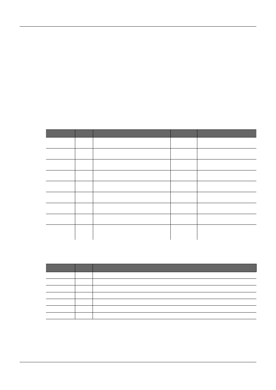
Table 24:
SATA Signal Description
Signal
Pin
Description
I/O
Comment
SATA0_RX+
SATA0_RX-
A19
A20
Serial ATA channel 0
Receive input differential pair.
I SATA
SATA0_TX+
SATA0_TX-
A16
A17
Serial ATA channel 0
Transmit output differential pair.
O SATA
SATA1_RX+
SATA1_RX-
B19
B20
Serial ATA channel 1
Receive input differential pair.
I SATA
SATA1_TX+
SATA1_TX-
B16
B17
Serial ATA channel 1
Transmit output differential pair.
O SATA
SATA2_RX+
SATA2_RX-
A25
A26
Serial ATA channel 2
Receive input differential pair.
I SATA
SATA2_TX+
SATA2_TX-
A22
A23
Serial ATA channel 2
Transmit output differential pair.
O SATA
SATA3_RX+
SATA3_RX-
B25
B26
Serial ATA channel 3
Receive input differential pair.
I SATA
SATA3_TX+
SATA3_TX-
B22
B23
Serial ATA channel 3
Transmit output differential pair.
O SATA
SATA_ACT#
A28
Serial ATA activity LED. Open collector
output pin driven during SATA command
activity.
O 3.3V
CMOS OC
Able to drive 10 mA
Table 25:
Serial ATA Connector Pin-out
Pin
Signal Description
1
GND
Ground
2
TX+
Transmitter differential pair positive signal
3
TX-
Transmitter differential pair negative signal
4
GND
Ground
5
RX-
Receiver differential pair negative signal
6
RX+
Receiver differential pair positive signal
7
GND
Ground
PICMG
®
COM Express
®
Carrier Board Design Guide
Rev. 2.0 / December 6, 2013
87/218