Lpc firmware hub, Appendix a: deprecated features – Kontron COMe Starterkit Eval T2 User Manual
Page 207
Appendix A: Deprecated Features
9.2.
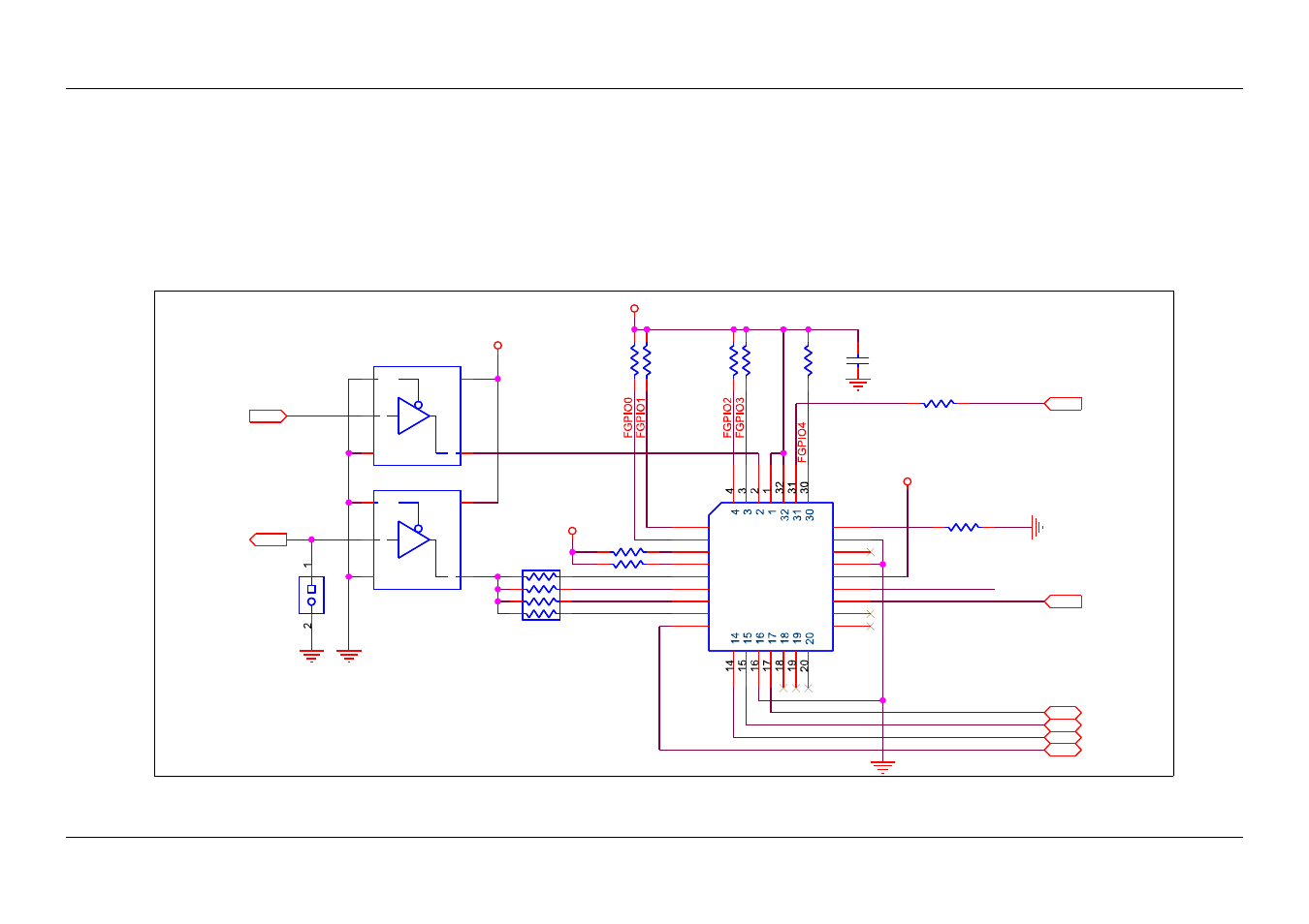
LPC Firmware Hub
An example of a Carrier Board Firmware Hub (FWH) implementation is shown in Figure 80: LPC Firmware Hub below. Use the FWH to store and
execute BIOS code.
A feature of the COM Express specification is the inclusion of the BIOS_DISABLE# pin. If this pin is pulled low on the Carrier Board, then the BIOS
on the Module is disabled. The BIOS can instead reside on the Carrier Board LPC or PCI buses. This is useful in some regulatory situations in which
it is required that regulatory technicians remove the BIOS, check its integrity, and replace it. There is usually room on a Carrier Board for a socketed
BIOS, whereas the Module BIOS is often a surface-mount device. The use of this feature is illustrated in the example below.
Figure 80:
LPC Firmware Hub
PICMG
®
COM Express
®
Carrier Board Design Guide Draft
Rev. 2.0 / December 6, 2013
207/218
ID0
ID1
ID2
ID3
FWH_RST#
FWH_RST#
VCC_3V3
VCC_3V3
VCC_3V3
VCC_3V3
CEX
LPC_AD0
CEX
LPC_AD1
CEX
LPC_AD2
CEX
LPC_AD3
CEX
LPC_FRAME#
CEX
BIOS_DISABLE#
CEX
CB_RESET#
CEX
LPC_CLK
short to enable
this FWH and
disable FWH on
CEX module
note: place serial resistor near CEX connector
J26
PLCC32
J26
PLCC32
5
5
6
6
7
7
8
8
9
9
10
10
11
11
12
12
13
13
21
21
22
22
23
23
24
24
25
25
26
26
27
27
28
28
29
29
R23 7
22R
R23 7
22R
R156
10k
R156
10k
U23
74125
U23
74125
OE#
1
A
2
GND
3
Y
4
VCC
5
R14 7
10k
R14 7
10k
C183
100n
C183
100n
R153
10k
R153
10k
R14 5
100k
R14 5
100k
R14 6
10k
R14 6
10k
R148
10k
R148
10k
J27
J27
U34
74125
U34
74125
OE#
1
A
2
GND
3
Y
4
VCC
5
R150
10k
R150
10k
RN1
56R
RN1
56R
2
1
3
4
5
6
7
8
R154
10k
R154
10k