Usb connector, Reference schematics – Kontron COMe Starterkit Eval T2 User Manual
Page 77
COM Express Interfaces
Table 18:
USB Signal Description
Signal
Pin
#
Description
I/O
Comment
USB0+
A46
USB Port 0, data + or D+
I/O USB
mandatory on Module
USB0-
A45
USB Port 0, data - or D-
I/O USB
mandatory on Module
USB1+
B46
USB Port 1, data + or D+
I/O USB
mandatory on Module
USB1-
B45
USB Port 1, data - or D-
I/O USB
mandatory on Module
USB2+
A43
USB Port 2, data + or D+
I/O USB
mandatory on Module
USB2-
A42
USB Port 2, data - or D-
I/O USB
mandatory on Module
USB3+
B43
USB Port 3, data + or D+
I/O USB
mandatory on Module
USB3-
B42
USB Port 3, data - or D-
I/O USB
mandatory on Module
USB4+
A40
USB Port 4, data + or D+
I/O USB
optional on Module
USB4-
A39
USB Port 4, data - or D-
I/O USB
optional on Module
USB5+
B40
USB Port 5, data + or D+
I/O USB
optional on Module
USB5-
B39
USB Port 5, data - or D-
I/O USB
optional on Module
USB6+
A37
USB Port 6, data + or D+
I/O USB
optional on Module
USB6-
A36
USB Port 6, data - or D-
I/O USB
optional on Module
USB7+
B37
USB Port 7, data + or D+
I/O USB
optional on Module
USB7-
B36
USB Port 7, data - or D-
I/O USB
optional on Module
USB_0_1_OC# B44
USB over-current sense, USB ports 0 and 1.
I 3.3V CMOS
optional on Module
USB_2_3_OC# A44
USB over-current sense, USB ports 2 and 3.
I 3.3VCMOS
optional on Module
USB_4_5_OC# B38
USB over-current sense, USB ports 4 and 5.
I 3.3V CMOS
optional on Module
USB_6_7_OC# A38
USB over-current sense, USB ports 6 and 7.
I 3.3V CMOS
optional on Module
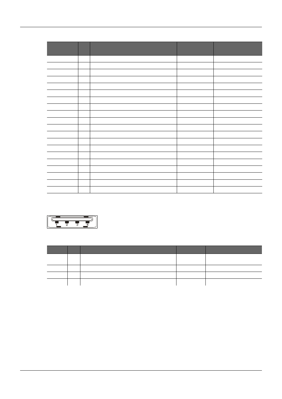
2.8.1.3.
USB connector
Figure 28:
USB Connector
Table 19:
USB Connector Signal Description
Signal
Pin Description
I/O
Comment
VCC
1
+5V Power Supply
P 5V
Must be current-limited for
external devices
-DATA
2
Universal Serial Bus Data, negative differential signal.
I/O USB
+DATA
3
Universal Serial Bus Data, positive differential signal.
I/O USB
GND
4
Ground
P
2.8.2.
Reference Schematics
The following notes apply to Figure 29 below.
J6 incorporate an USB Type A receptacle. J58 has two of them and in addition, includes an RJ-
45 (Foxconn UB11123-J51, Pulse JW0A1P0R-E).
The reference design uses an over-current detection and protection device. Two examples are
the Texas Instruments TPS2042AD and the Micrel MIC2026 dual channel power distribution
switch. The second example includes a discrete implementation.
PICMG
®
COM Express
®
Carrier Board Design Guide
Rev. 2.0 / December 6, 2013
77/218