Tv-out reference schematics – Kontron COMe Starterkit Eval T2 User Manual
Page 205
Appendix A: Deprecated Features
9.1.3.
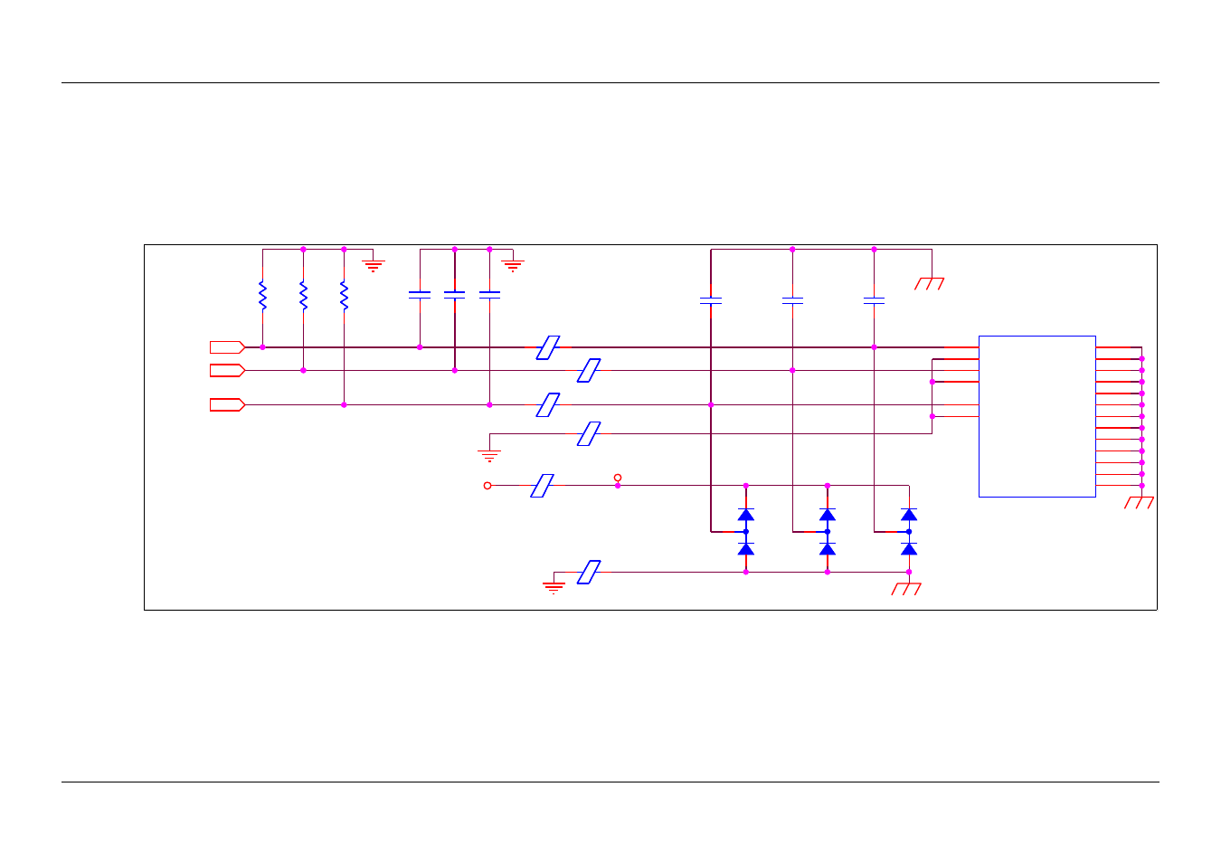
TV-Out Reference Schematics
All signals along the left edge of the figure below are sourced directly from the COM Express Module. No additional pull-ups or terminations beyond
what is shown in the figure are required.
The 150 Ω termination to ground is important both for signal integrity and to establish the correct DC level on the line. All components shown in this
figure should be placed close to the Carrier Board connector shown in the figure.
Figure 79:
TV-Out Reference Schematics
PICMG
®
COM Express
®
Carrier Board Design Guide Draft
Rev. 2.0 / December 6, 2013
205/218
GND_TV
C_C
Y_C
COMP_C
VCC_TVESD_5V0
VCC_5V0
CEX
TV_DAC_C
CEX
TV_DAC_B
CEX
TV_DAC_A
Note: Connection between logic GND and
chassis depends on grounding architecture.
Connect GND with chassis on a single point
even this connection is drawn on all schematic
examples throughout this document.
TV
D37
NUP1301
D37
NUP1301
1
2
3
C306
10p
C306
10p
D38
NUP1301
D38
NUP1301
1
2
3
C307
10p
C307
10p
C308
10p
C308
10p
D39
NUP1301
D39
NUP1301
1
2
3
FB106
50-Ohms@100MHz 3A
FB106
50-Ohms@100MHz 3A
C309
10p
C309
10p
FB5 9
120R / 0.6A
FB5 9
120R / 0.6A
J36
PINASJACK
J36
PINASJACK
GND
3
GND
4
Luminance
2
Chrominance
1
Composite
7
GND
6
SHLD0
H1
SHLD1
H2
SHLD2
H3
SHLD3
H4
SHLD4
H5
SHLD5
H6
SHLD6
A5
SHLD7
B5
SHLD8
C5
SHLD9
D5
SHLD10
E5
SHLD11
F5
SHLD12
5
R231
150R
R231
150R
R233
150R
R233
150R
FB10 4
120R / 0.6A
FB10 4
120R / 0.6A
C304
10p
C304
10p
R232
150R
R232
150R
FB60
50-Ohms@100MHz 3A
FB60
50-Ohms@100MHz 3A
FB10 5
120R / 0.6A
FB10 5
120R / 0.6A
FB10 3
120R / 0.6A
FB10 3
120R / 0.6A
C305
10p
C305
10p