Signal definitions, Status led signal definitions – Kontron COMe Starterkit Eval T2 User Manual
Page 70
COM Express Interfaces
2.7.
LAN
All COM Express Modules provide at least one LAN port. The 8-wire 10/100/1000BASE-T
Gigabit Ethernet interface compliant to the IEEE 802.3-2005 specification is the preferred
interface for this port, with the COM Express Module PHY responsible for implementing
auto-negotiation of 10/100BASE-TX vs 10/100/1000BASE-T operation. The carrier may also
support a 4-wire 10/100BASE-TX interface from the COM Express Module on an exception
basis. Check with your vendor for 10/100 only implementations.
2.7.1.
Signal Definitions
The LAN interface of the COM Express Module consists of 4 pairs of low voltage differential
pair signals designated from 'GBE0_MDI0' (+ and -) to 'GBE0_MDI3' (+ and -) plus additional
control signals for link activity indicators. These signals can be used to connect to a
10/100/1000BASE-T RJ45 connector with integrated or external isolation magnetics on the
Carrier Board. The corresponding LAN differential pair and control signals can be found on
rows A and B of the Module's connector, as listed in Table 16 below.
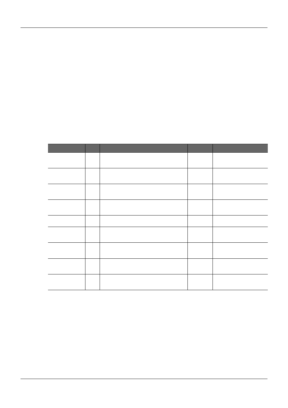
Table 16:
LAN Interface Signal Descriptions
Signal
Pin# Description
I/O
Comment
GBE0_MDI0+
GBE0_MDI0-
A13
A12
Media Dependent Interface (MDI) differential pair
0. The MDI can operate in 1000, 100, and
10Mbit/sec modes.
I/O GBE
This signal pair is used for all
modes.
GBE0_MDI1+
GBE0_MDI1-
A10
A9
Media Dependent Interface (MDI) differential pair
1. The MDI can operate in 1000, 100, and
10Mbit/sec modes.
I/O GBE
This signal pair is used for all
modes.
GBE0_MDI2+
GBE0_MDI2-
A7
A6
Media Dependent Interface (MDI) differential pair
2. The MDI can operate in 1000, 100, and
10Mbit/sec modes.
I/O GBE
This signal pair is only used
for 1000Mbit/sec Gigabit
Ethernet mode.
GBE0_MDI3+
GBE0_MDI3-
A3
A2
Media Dependent Interface (MDI) differential pair
3. The MDI can operate in 1000, 100, and
10Mbit/sec modes.
I/O GBE
This signal pair is only used
for 1000Mbit/sec Gigabit
Ethernet mode.
GBE0_CTREF
A14
Reference voltage for Carrier Board Ethernet
channel 0 magnetics center tap.
REF
GBE0_LINK#
A8
Ethernet controller 0 link indicator, active low.
O 3.3V
Suspend
OD CMOS
GBE0_LINK100#
A4
Ethernet controller 0 100Mbit/sec link indicator,
active low.
O 3.3V
Suspend
OD CMOS
GBE0_LINK1000#
A5
Ethernet controller 0 1000Mbit/sec link indicator,
active low.
O 3.3V
Suspend
OD CMOS
GBE0_ACT#
B2
Ethernet controller 0 activity indicator, active low. O 3.3V
Suspend
OD CMOS
2.7.1.1.
Status LED Signal Definitions
The four link status signals (LINK#, LINK100#, LINK1000#, and ACT#) are combined on the
carrier to drive two status LEDs (Link Activity and Link Speed). These two LEDs are typically
integrated into the RJ45 receptacle housing for the Ethernet, but may be placed on the
carrier Module assembly as discrete LEDs. The most common functional characteristics for
each LED are listed in Table 17 below.
PICMG
®
COM Express
®
Carrier Board Design Guide
Rev. 2.0 / December 6, 2013
70/218