Power monitoring circuit discussion – Kontron COMe Starterkit Eval T2 User Manual
Page 161
Power and Reset
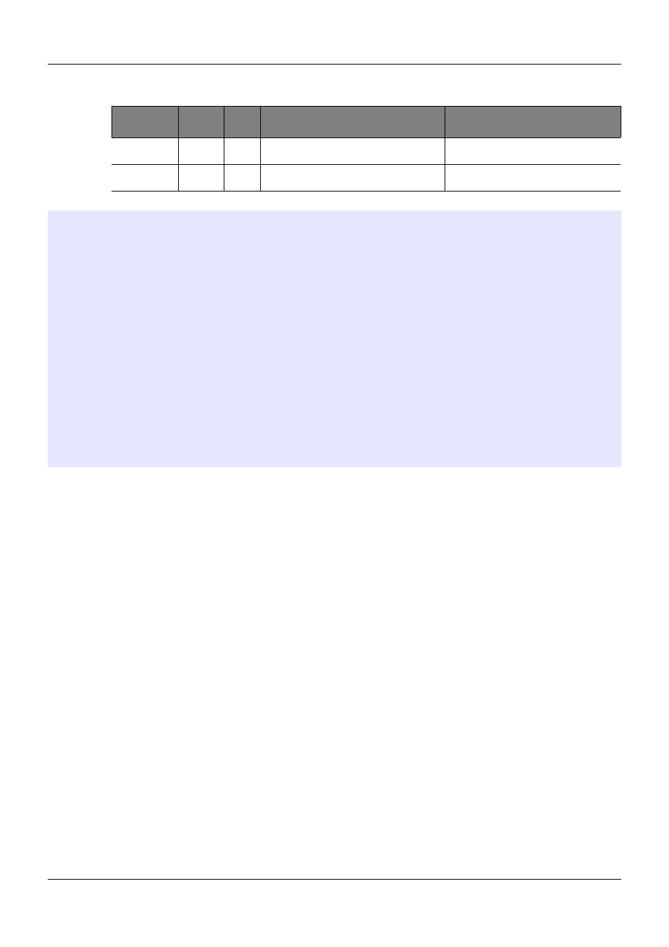
Table 53:
ATX and AT Power Up Timing Values
Parameter Min
Value
Max
Value
Description
Comments
TPB
10ms
500ms Push Button Power Switch – time to bring
Module chipset out of Suspend mode
Applies only to ATX Style Power Up
TPSR
0.1ms
20ms
Power Supply Rise Time
Notes
There is a period of time (TMP1 in Figure 64 and Figure 65 above) during which the Carrier
Board circuits have power but the COM Express Module main internal power rails are not
up. This is because almost all COM Express internal rails are derived from the external
VCC_12V and there is a non-zero start-up time for the Module internal power supplies.
Carrier Board circuits should not drive any COM Express lines during the TMP1 interval
except for those identified in the COM Express Specification as being powered from a
Suspend power rail. Almost all such signals are active low. Such signals, if used, should
be driven low by open drain Carrier Board circuits to assert them. Pull-ups, if present,
should be high value (10K to 100K) and tied to VCC_5V_SBY.
The line PWR_OK may be used during the TMP1 interval to hold off a COM Express
Module boot. Sometimes this is done, for example, to allow a Carrier Board device such
as an FPGA to be configured before the Module boots.
The deployment of Carrier Board pull-ups on COM Express signals should be kept to a
minimum in order to avoid back-driving the COM Express signal pins during this interval.
Carrier Board pull-ups on COM Express signal pins are generally not necessary – most
signals are pulled up if necessary on the Module.
3.2.4.
Power Monitoring Circuit Discussion
Contemporary chipsets used in COM Express Modules incorporate a state machine or micro-
controller that is powered from a Suspend power rail (i.e. a power rail that is derived from
VCC_5V_SBY and is on whenever the ATX power supply has incoming AC line power). This
state machine or micro-controller operates autonomously from the main CPU on the Module. The
function of this state machine or micro-controller is to manage the system power states. It
monitors various inputs (e.g. PWRBTN#, WAKE0#, WAKE1#, etc.) that can cause power state
changes, and outputs status signals (e.g. SUS_S5#, SUS_S4#, SUS_S3#, SUSPEND#) that can
be used by system hardware to control various power supplies and power planes in the system.
PICMG
®
COM Express
®
Carrier Board Design Guide
Rev. 2.0 / December 6, 2013
161/218