Vcc5_sby routing, Power state and reset signal routing – Kontron COMe Starterkit Eval T2 User Manual
Page 168
Power and Reset
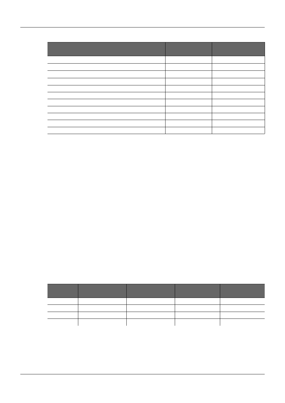
Table 56:
Approximate Copper Trace Current Capability per IPC-2221 Charts
Trace Type
Max Current with
10°C Temp Rise
Max Current with
20°C Temp Rise
100 mil wide internal trace ½ ounce/ 17μm base copper
1.3 A
1.8 A
200 mil wide internal trace ½ ounce/ 17μm base copper
2.0 A
3.0 A
400 mil wide internal trace ½ ounce/ 17μm base copper
3.5 A
5.0 A
100 mil wide internal trace 1 ounce/ 35μm base copper
2.1 A
3.0 A
200 mil wide internal trace 1 ounce/ 35μm base copper
3.5 A
5.2 A
400 mil wide internal trace 1 ounce/ 35μm base copper
6.0 A
8.0 A
100 mil wide external trace ½ ounce/ 17μm base copper
2.4 A
3.4 A
200 mil wide external trace ½ ounce/ 17μm base copper
4.0 A
5.5 A
400 mil wide external trace ½ ounce/ 17μm base copper
7.0 A
10.0 A
3.5.3.
VCC5_SBY Routing
The +5V Suspend power rail, if used, should be sized to handle 2A. Most, but not all, Modules
will use considerably less than 2A for this power rail. Modules with multiple Ethernet channels
and wake-on-LAN capability will use more current. The COM Express Specification allows up to
2A on this rail.
3.5.4.
Power State and Reset Signal Routing
Power state and reset signals are single-ended signals that do not have any particular routing
constraints.
To utilize the full functionality of PCI Express devices on the COM Express Carrier Board, some
additional supply voltages are necessary besides the standard supply voltages of the ATX power
supply. Many PCI Express devices are capable of generating wake up events during Suspend
operation; for example an external PCI Express Ethernet device that supports 'Wake On LAN'
functionality. Therefore, it is necessary to generate an additional 3.3V Suspend voltage on the
Carrier Board to supply such devices during Suspend operation. The voltage regulator must be
designed to meet the power requirements of the connected devices.
The PCI Express specification defines maximum power requirements for the different PCI
Express connectors and/or devices. The power supply for the Carrier Board must be designed to
meet these maximum power requirements. Table 57 below shows the maximum current
consumption defined for the different types of PCI Express connectors.
Table 57:
PCIe Connector Power and Bulk Decoupling Requirements
Power Rail
PCIe x1, x4 or x8
Connector
PCIe x16
Connector
ExpressCard
Connector
PCIe Mini Card
Connector
VCC_12V
2.1A @ 1000uF bulk
5.5A @ 2000uF bulk
VCC_3V3
3.0A @ 1000uF bulk
3.0A @ 1000uF bulk
1.35A
-
VCC_3V3_SB
375mA @ 150uF bulk
375mA @ 150uF bulk
275mA
2.75A
VCC_1V5
750mA
500mA
PICMG
®
COM Express
®
Carrier Board Design Guide
Rev. 2.0 / December 6, 2013
168/218