System management bus (smbus), Signal definitions, 19 'system management bus (smbus) – Kontron COMe Starterkit Eval T2 User Manual
Page 123
COM Express Interfaces
2.19.
System Management Bus (SMBus)
The SMBus is primarily used as an interface to manage peripherals such as serial presence
detect (SPD) on RAM, thermal sensors, PCI/PCIe devices, smart battery, etc. The devices that
can connect to the SMBus can be located on the Module and Carrier. Designers need to take
note of several implementation issues to ensure reliable SMBus interface operation. The SMBus
is similar to I2C. I2C devices have the potential to lock up the data line while sending information
and require a power cycle to clear the fault condition. SMBus devices contain a timeout to
monitor for and correct this condition. Designers are urged to use SMBus devices when possible
over standard I2C devices. COM Express Modules are required to power SMBus devices from
Early Power in order to have control during system states S0-S5. The devices on the Carrier
Board using the SMBus are normally powered by the 3.3V main power. To avoid current leakage
between the main power of the Carrier Board and the Suspend power of the Module, the SMBus
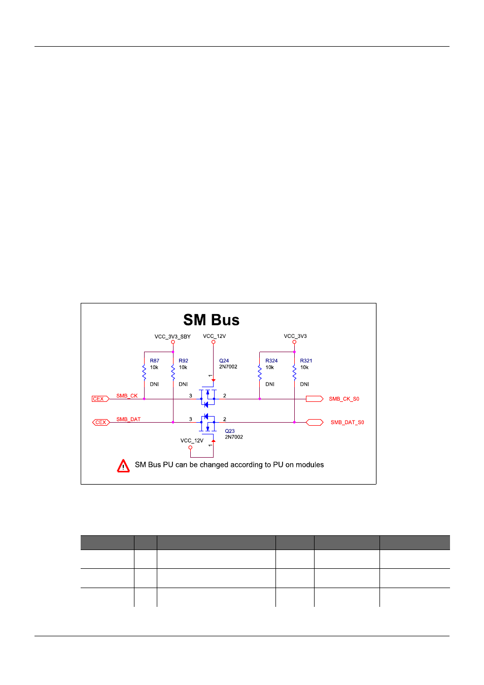
on the Carrier Board must be separated by a bus switch from the SMBus of the Module. Figure
48 below shows an appropriate bus switch circuit for separating the SMBus of the Carrier Board
from the SMBus of the Module. However, if the Carrier Board also uses Suspend powered
SMBus devices that are designed to operate during system states S3-S5, then these devices
must be connected to the Suspend powered side of the SMBus, i. e. between the COM Express
Module and the bus switch. Since the SMBus is used by the Module and Carrier, care must be
taken to ensure that Carrier based devices do not overlap the address space of Module based
devices. Typical Module located SMBus devices and their addresses include memory SPD
(serial presence detect 1010 000x, 1010 001x), programmable clock synthesizes (1101 001x),
clock buffers (1101 110x), thermal sensors (1001 000x), and management controllers (vendor
defined address). Contact your Module vendor for information on the SMBus addresses used.
Figure 48:
System Management Bus Separation
2.19.1.
Signal Definitions
Table 38:
System Management Bus Signals
Signal
Pin
Description
I/O
Pwr Rail
Comment
SMB_CK
B13
System Management Bus bidirectional
clock line
I/O OD
CMOS
3.3V
Suspend rail
SMB_DAT
B14
System Management bidirectional data
line.
I/O OD
CMOS
3.3V
Suspend rail
SMB_ALERT#
B15
System Management Bus Alert
I
CMOS
3.3V Suspend Rail
PICMG
®
COM Express
®
Carrier Board Design Guide
Rev. 2.0 / December 6, 2013
123/218