Speaker output, Power atx atx on, Power at – Kontron COMe Starterkit Eval T2 User Manual
Page 133: Type 2 detection, Com express interfaces, Picmg, Com express
COM Express Interfaces
2.22.2.
Speaker Output
The PC-AT architecture provides a speaker signal that creates beeps and chirps. The signal is a
digital-logic signal that is created from system timers within the core chipset. The speaker
provides feedback to the user that an error has occurred. The system BIOS usually drives the
speaker line with a set of beep codes to indicate hardware problems such as a memory test
failure, a missing video device, or a missing keyboard. Application software often uses the PC-
AT speaker to flag an error such as an invalid key press.
This speaker signal should not be confused with the analog-audio signals produced by the audio
CODEC. In many systems, the PC-AT speaker signal is fed into one of the audio CODEC inputs,
allowing it to be mixed with other audio signals and heard on the audio transducer (speakers and
headphones) that the CODEC drives.
The COM Express Module provides a speaker output signal called 'SPKR', which is intended to
drive an external FET or a logic gate to connect a PC speaker.
The 'SPKR' signal is often used as a configuration strap for the Modules chipset. It should not be
connected to a pull-up or pull-down resistor, which could overwrite the internal chipset
configuration and result in a malfunction of the Module.
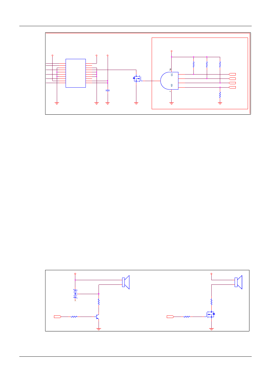
The PC-AT audio transducer that is used for error messages is usually a small, low-cost
loudspeaker or piezoelectric-electric buzzer. A buffering between the Module SPKR pin and the
audio transducer is required. An example circuit is shown in Figure 52 below. The net SPKR is
sourced from Module pin B32. If the transducer is a low impedance device, such as an 8 Ω
speaker, then a larger resistor value and package size for R173/R175 is in order.
Figure 52:
Speaker Output Circuitry
PICMG
®
COM Express
®
Carrier Board Design Guide
Rev. 2.0 / December 6, 2013
133/218
VCC_3V3
VCC_3V3
VCC_5V0
VCC_5V0
VCC_12V_CEX
VCC_12V
VCC_12V_CEX
VCC_5V_SBY
VCC_12V_CEX
VCC_5V_SBY
NO CONNECT
NO CONNECT
NO CONNECT
NO CONNECT
VCC_5V_SBY
CEX
PWR_OK
CEX
PWRBTN#
CEX
SLP_S3#
CEX
PWRBTN#
CEX
PWR_OK
CEX
SUS_S3#
CEX
TYPE2#
CEX
TYPE1#
CEX
TYPE0#
POWER ATX
ATX ON
note: PWR_OK is only
3.3V tolerant
POWER AT
note: only VCC_12V_CEX and VCC_5V_SBY are
needed by COM Express module
Type 2 Detection
J41
ATX_12V_Connector
J41
ATX_12V_Connector
GND
1
GND
2
+12V
3
+12V
4
X9
ATX Power Connector
X9
ATX Power Connector
+3.3V
1
+3.3V
2
GND
3
+5V
4
GND
5
+5V
6
GND
7
PG
8
5V_SB
9
+12V
10
+3.3V
11
-12V
12
GND
13
PS_ON#
14
GND
15
GND
16
GND
17
-5V
18
+5V
19
+5V
20
Power Connector
Power Connector
Q14
BS138
Q14
BS138
3
1
2
C202
100n
C202
100n
U1412A
74HCT21
U1412A
74HCT21
1A
1
1B
2
1C
4
1D
5
1Y
6
V
G
sh
SW1
PB_ON
sh
SW1
PB_ON
5
R1456
4k7
R1456
4k7
R1457
4k7
R1457
4k7
C203
100n
C203
100n
R1458
4k7
R1458
4k7
R1455
100k
R1455
100k
74VHC07
74VHC07
1
2
C232
100n
C232
100n
C201
100n
C201
100n
VCC_5V0
VCC_5V0
CEX
SPKR
CEX
SPKR
+
SPK2
Piezo Speaker
+
SPK2
Piezo Speaker
R169
22k
R169
22k
+
SPK1
Piezo Speaker
+
SPK1
Piezo Speaker
R174
100R
R174
100R
R173
75R
R173
75R
R175
33R
R175
33R
Q6
BC817
Q6
BC817
1
3
2
D29
BAT54A
D29
BAT54A
Q8
2N7002
Q8
2N7002
3
1
2