General purpose input/output (gpio) – Kontron COMe Starterkit Eval T2 User Manual
Page 138
COM Express Interfaces
2.22.6.
General Purpose Input/Output (GPIO)
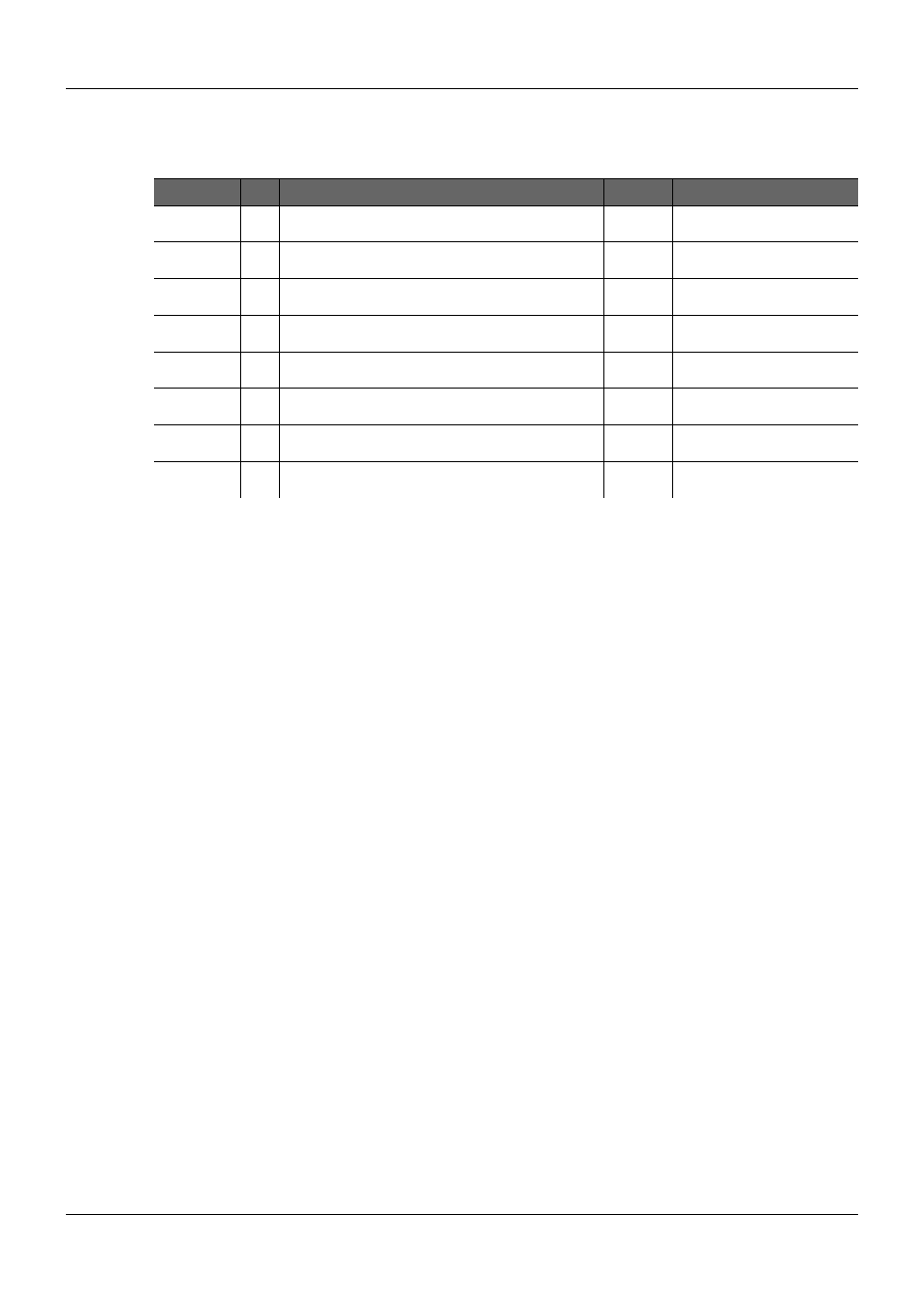
Table 46:
GPIO Signal Definition
Signal
Pin Description
I/O
Comment
GPI0
A54
General purpose input pins. Pulled high internally on the
Module.
I 3.3V
CMOS
GPI1
A63
General purpose input pins. Pulled high internally on the
Module.
I 3.3V
CMOS
GPI2
A67
General purpose input pins. Pulled high internally on the
Module.
I 3.3V
CMOS
GPI3
A85
General purpose input pins. Pulled high internally on the
Module.
I 3.3V
CMOS
GPO0
A93
General purpose output pins. Upon a hardware reset,
these outputs should be low.
O 3.3V
CMOS
GPO1
B54
General purpose output pins. Upon a hardware reset,
these outputs should be low.
O 3.3V
CMOS
GPO2
B57
General purpose output pins. Upon a hardware reset,
these outputs should be low.
O 3.3V
CMOS
GPO3
B63
General purpose output pins. Upon a hardware reset,
these outputs should be low.
O 3.3V
CMOS
PICMG
®
COM Express
®
Carrier Board Design Guide
Rev. 2.0 / December 6, 2013
138/218
- CP3003-SA uEFI BIOS (72 pages)
- CP3003-SA (36 pages)
- CP3002 (38 pages)
- CP3002-RC uEFI (64 pages)
- CP-RIO3-05 (42 pages)
- CP3002-RC (30 pages)
- CP342 (52 pages)
- CP930 (46 pages)
- CP932 (52 pages)
- CP346 (72 pages)
- CP384 (66 pages)
- CP383 (74 pages)
- CP382 (58 pages)
- CP381 (60 pages)
- CP372 (64 pages)
- CP371 (60 pages)
- CP-RIO3-04S (38 pages)
- CP390 (36 pages)
- CPS3410 (9 pages)
- CPS3402 (9 pages)
- CPS3105 (9 pages)
- CPS3101 (9 pages)
- CPS3003-SA (19 pages)
- PB-SIO4 (34 pages)
- PB-SIO4A (34 pages)
- PB-DOUT8 (34 pages)
- VMOD-2 (82 pages)
- VSBC-32 (110 pages)
- VM42 (62 pages)
- Bootstrap Loader (24 pages)
- VMP1 with Netbootloader (120 pages)
- VMP1 (106 pages)
- NetBootLoader (86 pages)
- VMP2 (142 pages)
- VMP3 (154 pages)
- CP-RIO6-923 (32 pages)
- CP-RIO6-923-F (32 pages)
- CP-RIO6-001 (28 pages)
- CP-RIO6-001-HD-VGA (46 pages)
- CP-RIO6-M (20 pages)
- CP-RIO6-B (28 pages)
- CP6925 (42 pages)
- CP6002 uEFI BIOS (76 pages)
- CP6002 IPMI (40 pages)
- CP6002 (42 pages)