Kontron COMe Starterkit Eval T2 User Manual
Page 149
COM Express Interfaces
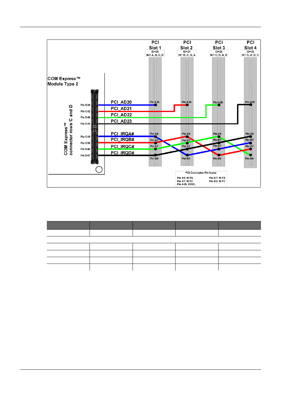
Figure 59:
PCI Bus Interrupt Routing
Most of these PCI devices only utilize the interrupt signal 'INTA#'. To distribute the interrupt
source of the devices over the interrupt signals 'INTB#', 'INTC#' and 'INTD#', an interrupt cross
routing scheme has to be implemented on the COM Express Carrier Board design. Figure 59
above and Table 49 below illustrate the PCI bus interrupt routing for the PCI bus slots 1-4.
Table 49:
PCI Bus Interrupt Routing
Device Signal
Slot / Device 1
Slot / Device 2
Slot / Device 3
Slot / Device 4
IDSEL
PCI_AD[20]
PCI_AD[21]
PCI_AD[22]
PCI_AD[23]
INTA#
PCI_IRQ[A]#
PCI_IRQ[B]#
PCI_IRQ[C]#
PCI_IRQ[D]#
INTB# (if used)
PCI_IRQ[B]#
PCI_IRQ[C]#
PCI_IRQ[D]#
PCI_IRQ[A]#
INTC# (if used)
PCI_IRQ[C]#
PCI_IRQ[D]#
PCI_IRQ[A]#
PCI_IRQ[B]#
INTC# (if used)
PCI_IRQ[D]#
PCI_IRQ[A]#
PCI_IRQ[B]#
PCI_IRQ[C]#
Requests and Grants cannot be shared. There should only be a single REQ / GNT pair per
device.
PICMG
®
COM Express
®
Carrier Board Design Guide
Rev. 2.0 / December 6, 2013
149/218