Hapter, Configuring the outer control loop, The outer control loop – Rockwell Automation FlexPak 3000 Digital DC Drive Version 4.3 User Manual
Page 95: Is shown in figure 9.1. the, Can be configured as a, Type 3 position regulator, which inputs the, Output directly into the current minor loop, Other, Schemes. to configure the, P.809)) equal to zero (this sets the
Configuring the Outer Control Loop
9-1
C
HAPTER
9
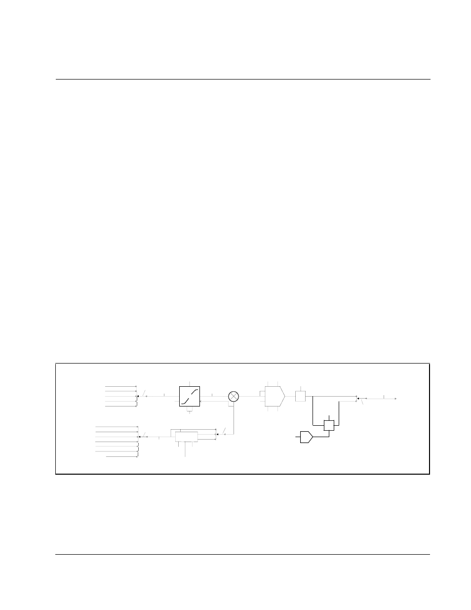
Configuring the Outer Control Loop
The outer control loop (
OCL
) is typically used to provide dancer position or tension
control in a web processing system. The
OCL
trims the speed/voltage loop reference
signal. The block diagram for the
OCL
is shown in figure 9.1.
The
OCL
can be configured as a:
•
Type 1 position regulator, which uses proportional-only control in the forward path.
•
Type 2 position regulator, which uses proportional-plus-integral control to reduce
steady state error to zero.
•
Type 3 position regulator, which inputs the
OCL
output directly into the current minor
loop.
•
Other
OCL
schemes.
To configure the
OCL
as a type 1 position regulator, set the lead break frequency (
OCL
PI
LEAD
FREQ
(P.809)) equal to zero (this sets the
PI
block to proportional only).
To configure the
OCL
as a type 2 position regulator, set the lead break frequency (
OCL
PI
LEAD
FREQ
(P.809)) to a non-zero value.
When enabled, the
OCL
executes every 20 msec.
Important: Scaling units of some
OCL
parameters are not predefined and must be set
by you. See the
OIM
manual to create
OCL
user-defined units.
Figure 9.1 – Outer Control Loop Block Diagram
OCL REF REGISTER
*REGISTER
ANALOG IN 1
ANALOG IN 2
FREQUENCY IN
NETW IN REG 1, 2, 3
From Network
(OCL REFERENCE)
{
OCL
REFERENCE
SELECT
OCL FEEDBACK
SELECT
(OCL RAMP
OUTPUT)
OCL REF
ROUNDING
S-CURVE
OCL REF
RAMP TIME
OCL
LEADLAG
SELECT
output of OCL
enable logic
SMOOTHING
RST\
ACC
DEC
INITV
+
–
output of OCL
enable logic
OCL PI
PROP GAIN
OCL PI
POSITIVE LIMIT
OCL PI
LEAD FREQ
OCL PI
NEGATIVE LIMIT
KP
HI
WLD
LO
RST\
INITV
PI
GAIN
MUL
OCL TRIM RANGE
(OCL OUTPUT)
*BYPASS
LEAD/LAG
LAG/LEAD
OCL LEADLAG
RATIO
OCL LEADLAG
LOW FREQ
(OCL FEEDBACK)
output of OCL
enable logic
INITV
L/L
WLD
RST\
RATIO
CML FEEDBACK
A N A L O G I N 1
ANALOG IN 2
(CML FEEDBACK)
8 sample average
{
*NONE
SPD LOOP OUTPUT
ANALOG AUTO REFERENCE
SPD LOOP OUTPUT
ANALOG AUTO REFERENCE
GAIN
MUL
TOP SPEED
SPEED RAMP OUTPUT
(in RPM)
ABS
DIV
ENABLED
*DISABLED
OCL PROP
TRIM SELECT
NETW IN REG 1, 2, 3
From Network
From Figure 11.2, A n a l o g
Inputs Block Diagram
From Figure 11.2, A n a l o g
Inputs Block Diagram a n d
Figure 11.4, F r e q u e n c y
Input Block Diagram
To Figure 4.7,
S p e e d R e f e r e n c e
M o d e S e l e c t
B l o c k D i a g r a m
To Figure 6.1,
C M L R e f B l o c k
D i a g r a m