3 configuring the armature current feedback – Rockwell Automation FlexPak 3000 Digital DC Drive Version 4.3 User Manual
Page 76
6-6
FlexPak 3000 DC Drive Software Reference
6.3
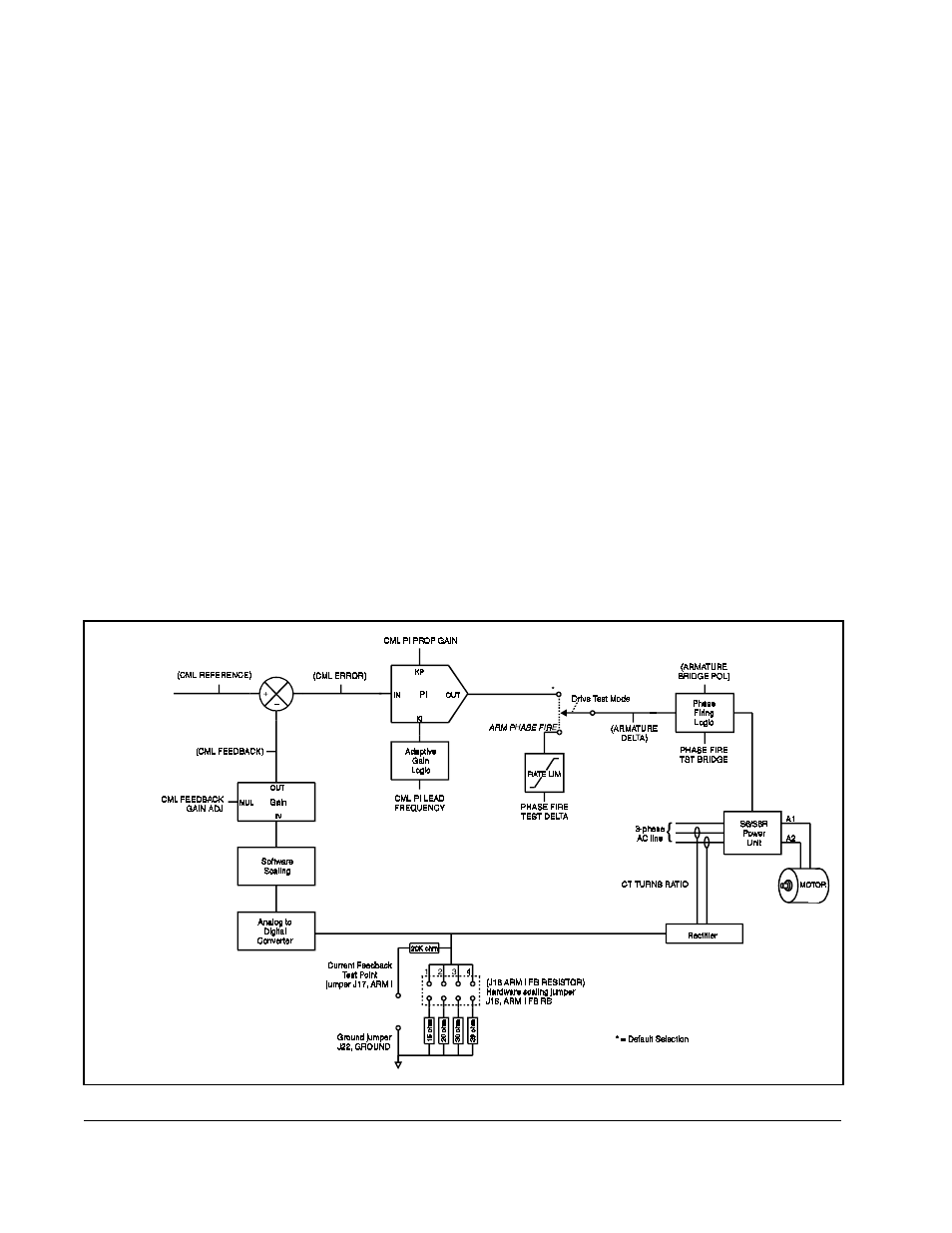
Configuring the Armature Current Feedback
Current transformers and a rectifier bridge are used to determine the armature current
feedback signal that is scaled by a burden resistor (hardware scaling). Ideally, the
selected burden resistor would scale the feedback signal so that 3 volts corresponds
to
MAXIMUM
CURRENT
(P.007). However, since burden resistor selection is limited to
one of four values, it is likely that none of the available burden resistors will result in
ideal scaling. Therefore, software scaling is used to adjust the output of the A/D
converter to the appropriate level. The FlexPak 3000 drive automatically calculates
and sets the software scale factor based on
CT
TURNS
RATIO
(P.010),
MOTOR
RATED
ARM
AMPS
(P.008), and
MAXIMUM
CURRENT
(P.007). After these parameters have been
set appropriately, hardware jumper J18 must be set according to parameter
J
18
ARM
I
FB
RESISTOR
(P.395).
An additional gain block in the feedback path allows you to adjust the current feedback
signal by a maximum of ±10% (gain range of 0.900 to 1.100). The
CML
FEEDBACK
GAIN
ADJ
(P.300) is typically set for unity gain.
The FlexPak 3000 drive limits the combination of the two gains (software and user
scale factors) to a range of 0.800 and 2.000. For example, suppose the FlexPak 3000
drive sets the software scale factor to 1.950.
CML
FEEDBACK
GAIN
ADJ
(P.300) is limited
to a maximum value of 1.025 (2.000/1.950) to prevent the combined gain from
exceeding 2.000.
The scaled
CML
feedback value appears as
CML
FEEDBACK
(P.397).
See figure 6.2 for block diagram.
Figure 6.2 – Current Minor Loop Block Diagram
From Figure 6.1, Current
Minor Loop Reference
Path Block Diagram