Rockwell Automation 1397 DC Drive Firmware 2.xx User Manual
Page 97
4–25
Start–Up and Adjustment
Publication 1397-5.0 — June, 2001
!
ATTENTION: The Drive will not operate at the
correct speed if jumpers J11 and J14 are not set to the
correct positions. Failure to observe this precaution could
result in damage to, or destruction of, the equipment.
The expected analog tachometer voltage range can be set to a
maximum of 250 or 62V DC. Jumper J11 selects the hardware
circuitry to maximize the resolution over the entire speed range.
Table 4.I
Regulator Board Jumpers
Jumper J14
Jumper J11
Top Speed Tach Volts
≤ 16 Volts
Low
16
Top Speed Tach Volts
≤ 31 Volts
Low
31/125
Top Speed Tach Volts
≤ 62 Volts
Low
62/250
Top Speed Tach Volts
≤ 125 Volts
High
31/125
Top Speed Tach Volts
≤ 250 Volts
High
62/250
Note: The output voltage of the tachometer must not exceed 250 V for DC tachometers or 275 RMS for
AC tachometers when the motor is rotating at [Max Motor Speed]. To calculate the output
voltage at top speed, multiply the two parameter values:
Tach Voltage at [Max Motor Speed] = [Max Motor Speed]
× [Analog Tach v per thousand]
1000
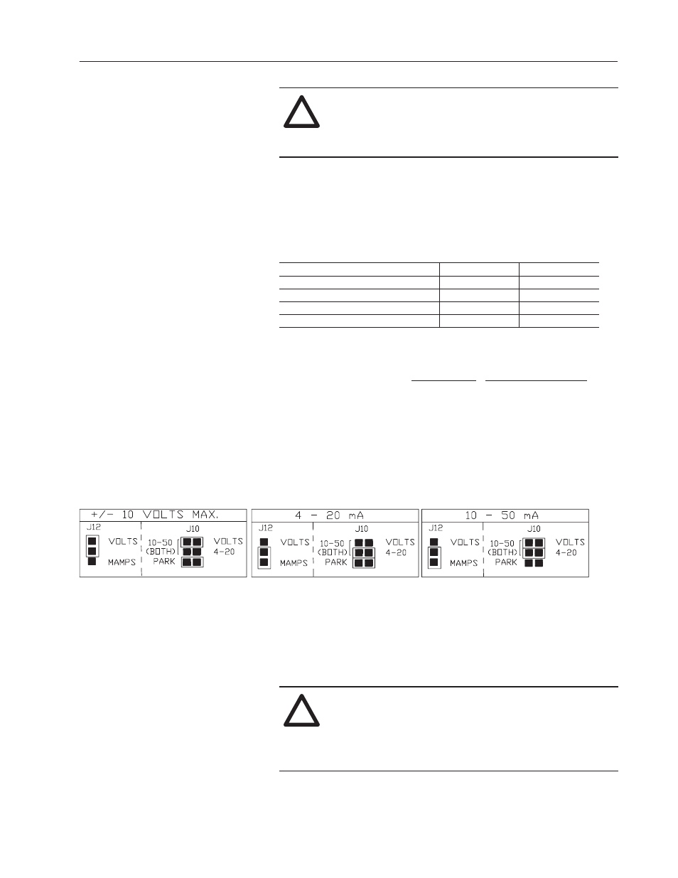
Analog Reference 1 Set–up (Jumpers J12, Autoref and J10, Autoref)
The Anlg In 1 jumpers (J12 and J10 Fig. 4.10) select the type of
analog reference to be used. J12 selects the type of signal (voltage or
milliamps). J10 selects the range.
Figure 4.10
Anlg In 1 Jumper Selection
Scaling the Armature Current Feedback (Jumper 18)
The Arm I FB RB jumper (J18) scales the armature current feedback
signal. The Drive calculates the value of the burden resistor needed
to scale the armature current feedback signal. The calculations are
based on the values of [Motor Arm Amps] (P.045 ) and Maximum
Current (P. 040).
!
ATTENTION: The Drive will not operate at the
correct speed if jumpers J10, J12 and J18 are not set to
the correct positions for your application. Failure to
observe this precaution could result in damage to, or
destruction of, the equipment.