Figure 2.25 wiring customer interlocks – Rockwell Automation 1397 DC Drive Firmware 2.xx User Manual
Page 54
2–36
Installation
Publication 1397-5.0 — June, 2001
Figure 2.24
CON 2 Terminal Strip 115 VAC Inputs
1
2
3
4
5
6
7
8
9
10
11 12
13 14
115V
HI L1
COAST
ST
OP
(IN6)
CUST
OMER
INTERLOCK (IN7)
115V
HI (L1)
RUN (IN1)
ST
OP (IN2)
JOG (IN3)
REV/FWD (IN4)
REF SELECT (IN5)
FAUL
T RESET (IN8)
115V HI (IN8)
BRUSH WEAR (IN9)
MOT
OR
THERMOST
A
T
(IN 10)
115V HI (L1)
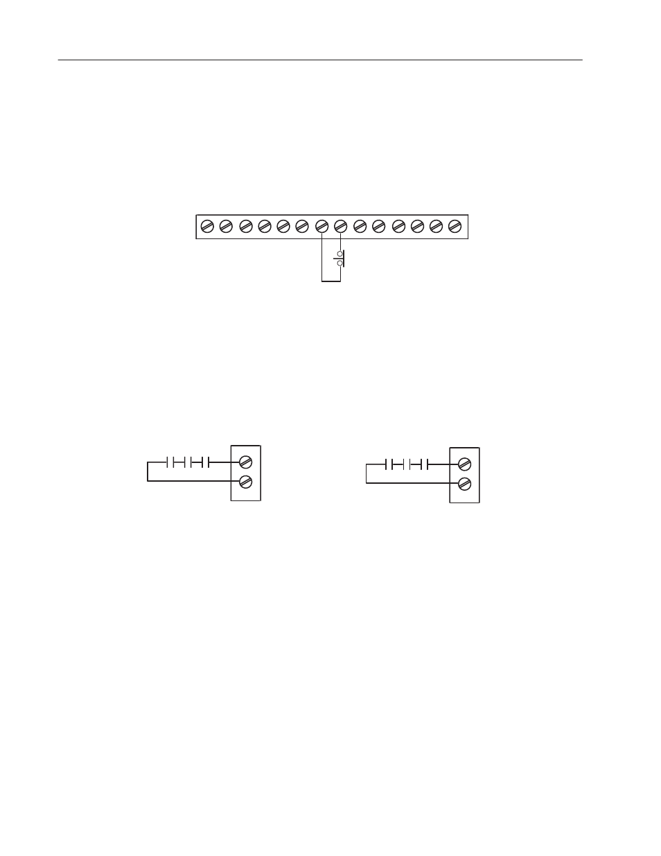
2. Wiring Customer Interlocks
Wire the Customer Interlock as shown in Figure 2.25. Both the 24V
Regulator Board Terminal Strip and the 115VAC CON2 Terminal
Strip utilize terminal #9 and #11 as the connection point for a
Customer Interlock. All customer interlocks must be closed for
Drive operation and CANNOT be masked.
Regulator Board Terminal Strip
24VDC Customer Interlock Circuit
9
11
115VAC Option Board CON 2
115VAC Customer Interlock Circuit
Figure 2.25
Wiring Customer Interlocks
9
11
Customer
Interlock (IN7)
115VAC Customer
Interlock Circuit
3. Wiring the Motor Thermostat/Brush Wear Circuits
Either a 24VDC or 115VAC input can be used to receive an external
voltage for a normally closed contact used in a motor thermostat
circuit. As shown in Figure 2.26, Terminal 13 is used for the motor
thermostat circuit on both 24VDC and 115VAC configurations. If
the motor thermostat circuit is open, the Drive will display a fault
and coast to a stop.
Terminal 12 is used for a level sensitive input that triggers a motor
brush wear alarm. The Drive will continue to operate under this
condition. Both the MOTOR BRUSH WEAR and MOTOR
THERMOSTAT inputs are always active and CANNOT be masked.