Rockwell Automation 1397 DC Drive Firmware 2.xx User Manual
Page 93
4–21
Start–Up and Adjustment
Publication 1397-5.0 — June, 2001
IMPORTANT: Jumpers are read only on powerup, so power must be
cycled for a change to a jumper setting to be recognized by the
Drive.
To set the jumpers:
1. Remove power from the Drive. Remove the cover. Refer to
Chapter 3 for cover removal. You do need to remove the HIM
bracket.
2. The jumpers are located on the regulator board as shown in
Figure 4.9.
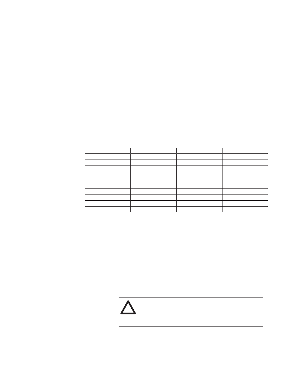
3. Change the jumper settings as described in the following
description and record them in the Final Setting column of
Table 4.G.
Table 4.G
Jumper and Adjustment Settings
Jumper/Adjustment
Default Setting
Calculated Setting
Final Setting
J15 (Regulator Type)
Speed
J16 (Program Protection)
Not Currently Used
J20 (Field Loss Detect)
Enable
J21 (Field Supply Jumper)
N/A
1
J19 (Analog Ref 2)
Pot
J14 (Tach V Range)
62
J11 (Tach V Scale)
16
J10 (Analog Ref 1)
Volts
J12 (Analog Ref 1)
Volts
J18 (ARM I FB RB)
Position 4
1
Only applicable when the optional Enhanced Field Supply kit is installed.
Setting the Regulator Type (Jumper J15)
J15 determines whether the Drive uses speed/voltage or
torque/current regulation mode. This jumper is read only when the
regulator is powered up.
When Current is selected, all speed references become torque
references. For example: Analog Ref 1 and Ref 2 are now Torque
References.
Also note that speed/voltage parameters must be set to provide
overspeed protection for the Drive.
!
ATTENTION: Failure to correctly set speed/voltage
parameters could result in dangerously high motor
speeds. Failure to provide overspeed protection could
result in bodily injury or equipment damage.