Monitor 1 source] — p.104, Monitor 1 level] — p.105 – Rockwell Automation 1397 DC Drive Firmware 2.xx User Manual
Page 150
5–40
Programming Parameters
Publication 1397-5.0 — June, 2001
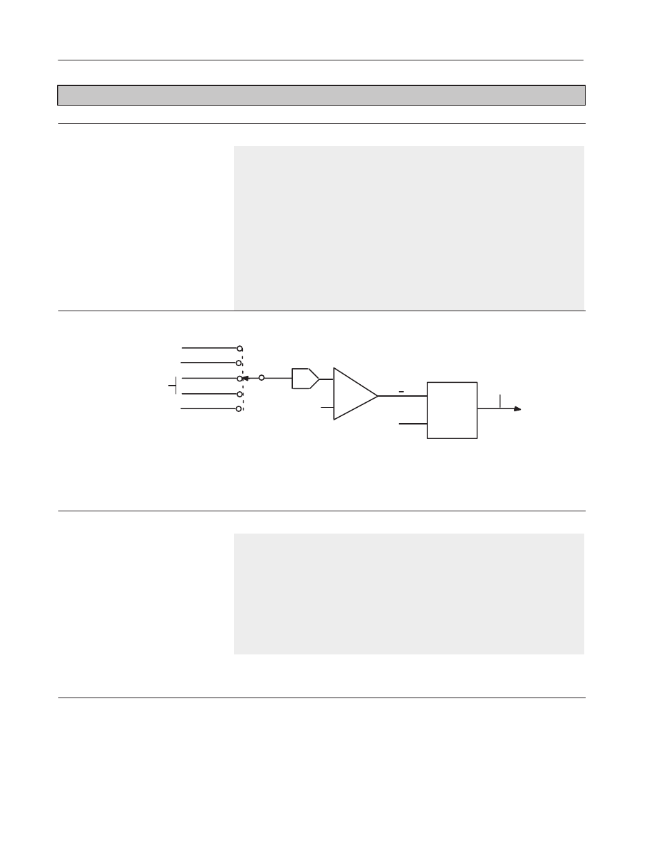
FEATURE SELECT
[Monitor 1 Source] — P.104
Selects the signal that drives monitor 1.
Display/Drive Units:
Numeric/Text
Parameter Range:
0 = Cur Lp Fdbk
1 = Spd Lp Fdbk
2 = Spd Ramp Out
3 = Spd Ramp In
4 = Spd Src Out
Parameter Type:
Configurable
Group:
Feature Select
Factory Default:
1 (Spd Lp Fdbk)
Minimum Value:
0
Maximum Value:
4
Monitor 1
Output
(P13)
To I/O
Expansion
Outputs
Block Diagram
COMPARE
A
B
Monitor 1 Delay
(P103)
Start/Stop
Delay Time
TIMER
A > B
ABS
Monitor 1 Level
(P105)
Cur Lp Fdbk
Spd Lp Fdbk
Spd Ramp Out
Spd Ramp In
Spd Src In
Current Loop
Feedback Average
From Speed Loop Block Diagram
From Speed Reference
Ramp Block Diagram
From Speed Reference
Source Block Diagram
[Monitor 1 Level] — P.105
The threshold for level detector 1. Refer to
the Level Detectors block diagram (Fig.
A.12) for additional information.
When the absolute value of the signal driving
monitor 1 is
≥ this threshold, the associated
timer starts. If the input signal is < this
threshold, the timer is immediately reset and
the level detector output is set to off.
Display/Drive Units:
%
Default Setting:
10.0%
Parameter Type:
Tunable
Group:
Feature Select
Factory Default:
10.0%
Minimum Value:
0.1%
Maximum Value:
100.0%
The parameter range for the level detector is automatically rescaled for speed or current based on the input selected by [Monitor 1 Source]. If
[Cur Loop Fdbk] is selected for [Monitor 1 Source], the parameter range is 0.1 to [Maximum Current]. For any other [Monitor 1 Source]
settings, the parameter range is 0.1 to 100.0%.