Rockwell Automation 1397 DC Drive Firmware 2.xx User Manual
Page 244
CE Conformity
B–12
Publication 1397-5.0 — June, 2001
Wiring the AC Line Inductor – Install the Line Inductor between
the line filter and the AC power input of the 1397 Drive as shown in
Figure B.9.
Wiring the Motor – Field and armature circuit wiring that is
internal to the electrical cabinet must be:
D Separated from all other wiring on the panel
D As close to the ground plane as possible. This is especially
important if an inverting fault breaker or dynamic braking circuit
is part of the armature circuit.
The external motor wiring must be run in a shielded cable or
continuous conductive conduit. The motor shunt field and armature
leads can be run together in the same cable. A ground wire must be
run that bonds the motor to the system star ground. Refer to Figure
B.6 for proper connection of the conduit shield and bonding wire.
Motor cable length is a major contributor to common mode
conducted emissions. The 1397 mains filters are sized for up to 75
meters (250 feet) of shielded motor power cables (total installed
length). If your installation requires a greater length, contact
Allen-Bradley.
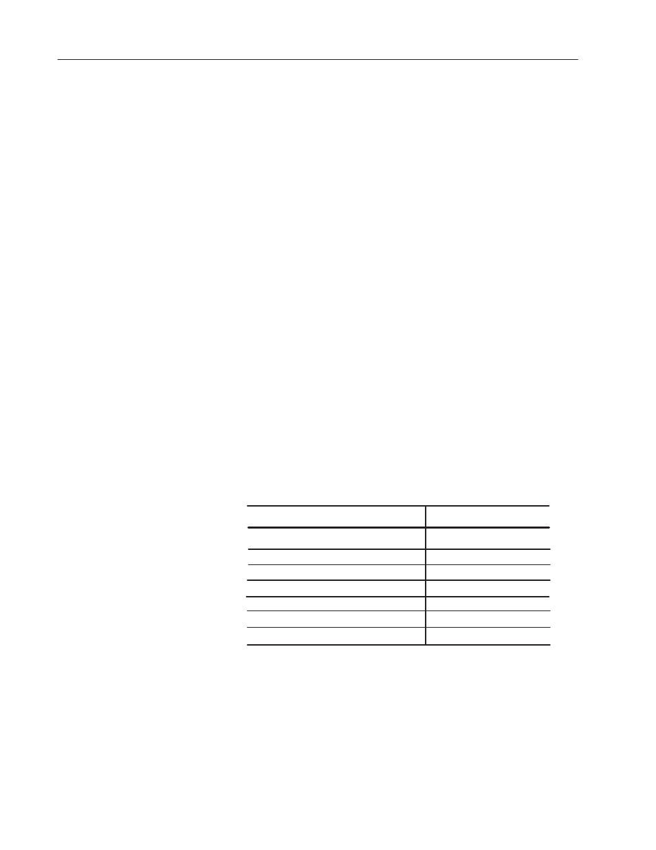
Wiring the Kits – The Bulletin 1397 has a number of option kits.
The kits listed in Table B.D are EMC benign – they have no impact
on the EMC compliance of the product if properly installed. See the
appropriate kit Instruction Manuals for installation and wiring
information.
115 VAC Control Interface
460 VAC to 230 VAC Fuse Conversion
AC Line Disconnect
Blower Motor Starter
Enhanced Field Supply
Field Current Regulator
Inverting Fault Circuit Breaker
Table B.D
1397 EMC – Benign Kits
Kit Name
Model Number
1397 – LII
1397 – FC
1397 – DS
1397 – MB
1397 – FS3
1397 – FS2
1397 – IFB
I/O Expansion Board (Model Number 914FK0101) – Wiring
connected to this board must be run in shielded cable or continuous
conductive conduit.