Rockwell Automation 1397 DC Drive Firmware 2.xx User Manual
Page 57
2–39
Installation
Publication 1397-5.0 — June, 2001
The JOG connection is made at terminal 4 on both 24VDC and
115VAC terminal strips. The Drive will jog when this input is
asserted, if the Drive is Ready and not already Running. This input
can be masked through the [Jog Mask] (P. 203) or [Logic Mask]
(P. 207).
The DIRECTION connection is made at terminal 5 on both 24VDC
and 115VAC terminal strips. This level sensitive input selects
between Forward (= 0) and Reverse (= 1). This parameter can be
masked through the [Direction Mask] (P. 202) or [Logic Mask]
(P. 207) parameters.
The REFERENCE SELECT connection is made at terminal 6 on
both 24VDC and 115VAC terminal strips. This level sensitive input
selects between ANALOG REFERENCE 1 (= 1) and ANALOG
REFERENCE 2 (= 0) parameters to be used as the reference to the
Drive. This parameter can be masked through the [Reference
Mask] (P.204) or [Logic Mask] (P. 207) parameters. NOTE: If an
I/O expansion board is installed, the Preset Speed selection bits will
override the reference selected by this input.
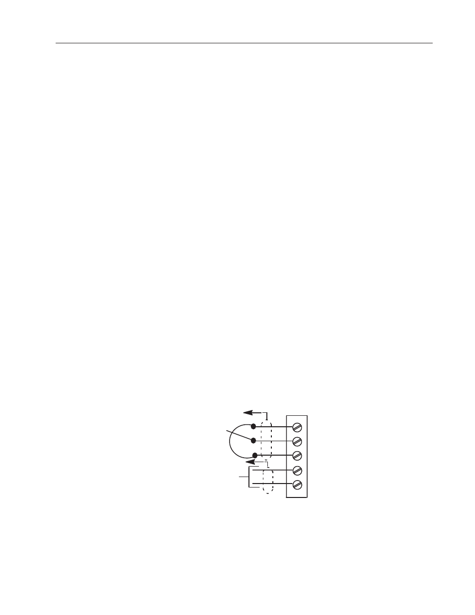
6. Wiring the Analog Input Circuits
Terminals TB16 thru TB23, as shown in Figure 2.29 are used for
reference and feedback signals.
ANALOG REFERENCE 2 is a fixed
± 10 VDC reference which is
connected at terminals 16, 17 and 18.
ANALOG REFERENCE 1 which is connected at Terminals TB19
and TB20 is a selectable signal type reference determined by [Anlg
In 1 Type] (P. 128) and regulator board jumpers J10 and J12.
ANALOG REFERENCE 1 can be set for 0-10 VDC,
±10 VDC,
4-20mA or 10-50 mA.
Figure 2.29
Regulator Board Terminal Strip
Analog Input Connections
16
17
18
+
+10V (ISOL)
19
20
–
Analog Ref 2
Analog Ref 1
+
–
PLC END
PLC END