Rockwell Automation 1397 DC Drive Firmware 2.xx User Manual
Page 105
4–33
Start–Up and Adjustment
Publication 1397-5.0 — June, 2001
Analog Tachometer Polarity Checks (Armature Voltage Control)
!
ATTENTION: Prior to running polarity checks, you
must provide a hardwired maintained external operator
accessible coast/stop pushbutton at regulator board
terminals 7 and 8 to disable the machine in case of
improper operation. Uncontrolled machine operation
can result if this is not done. Failure to observe this
precaution could result in severe bodily injury or loss
of life.
1. Verify that [Feedback Type] (P. 039) is set to DC Tach.
2. Verify that the tach is properly terminated by monitoring [Anlg
Tach Fdbk] (P. 194) when the motor is rotated in the same
direction as it was in Step 6 of the Motor and Feedback Polarity
checks.
3. The value in [Anlg Tach Fdbk] (P. 194) should be positive.
4. If the value observed is negative, remove power from the Drive
and reverse the tachometer connections terminated at the Drive.
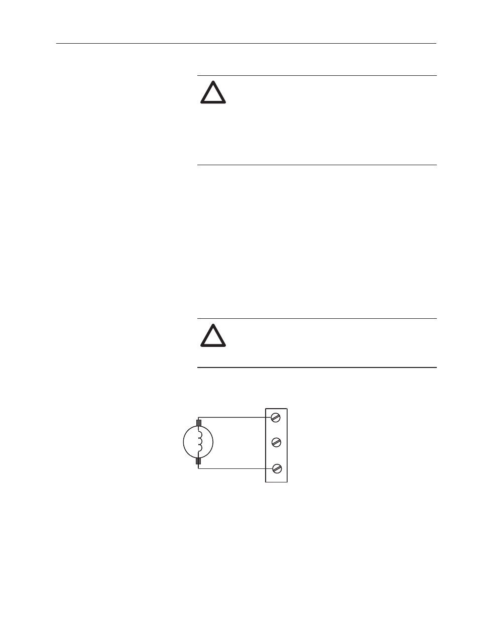
DC tachometers are terminated at terminals 21 and 23 (high
voltage range) or 22 and 23 (low voltage range) of the regulator
terminal strip (Figure 4.15).
!
ATTENTION: The Drive can overspeed if jumper J14
is set incorrectly, or the tach is wired incorrectly.
Failure to observe this precaution could result in
damage to the drive or process equipment.
Regulator Board Terminal Strip
High Voltage DC Tach Terminations
21
22
23
HI–RANGE
LO–RANGE
Common
Figure 4.15
DC Tach Installation
5. Proceed to verification of Drive Calibration.