Rockwell Automation 1397 DC Drive Firmware 2.xx User Manual
Page 56
2–38
Installation
Publication 1397-5.0 — June, 2001
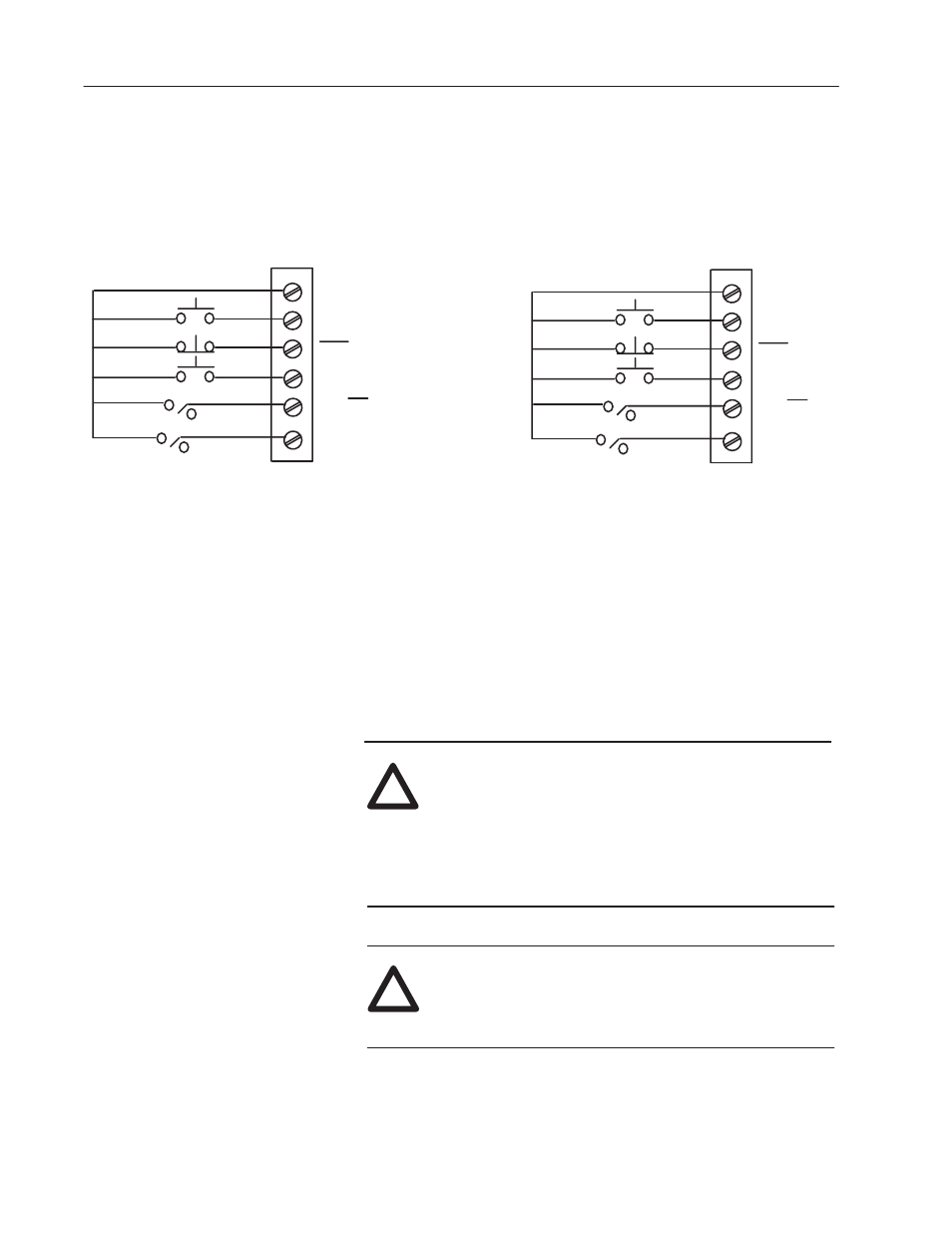
5. Wiring the Control I/O Circuits
Both the 24VDC and 115VAC control circuits use the # 1 thru #6
terminals on their respective terminal strips for control functions as
shown in Figure 2.28.
Regulator Board Terminal Strip
24VDC Control I/O Connections
1
2
3
STOP
RUN
+24V
115VAC Option Board CON 2
115VAC Control I/O Connections
4
5
6
REV
FWD
ANLG REF2
ANLG REF1
JOG
REV/FWD
REF SELECT
1
2
3
STOP (IN2)
RUN (IN1)
+115V (L1)
4
5
6
REV
FWD
ANLG REF2
ANLG REF1
JOG (IN3)
REV/FWD (IN4)
REFERENCE
SELECT (IN5)
Figure 2.28
Control I/O Wiring
The RUN connection is made at terminal 2 on both 24VDC and
115VAC terminal strips. The Run input is latched and therefore does
not have to be maintained to keep the Drive Running. This input can
be masked through the [Run Mask] (P. 201) or [Logic Mask]
(P. 207) parameter.
The STOP connection is made at terminal 3 on both 24VDC and
115VAC terminal strips. The stopping mode is determined by the
[Stop Mode Type] (P. 115). This input CANNOT BE MASKED.
!
ATTENTION: If Dynamic Braking is used as an
alternative stopping method, DO NOT use a hardwired
Stop device that removes AC line power. This will
de-energize the shunt field, causing a loss of the DB
effect and the motor will coast to a stop. Hazards to
personnel may exist if the machine is allowed to coast
to a stop.
!
ATTENTION: You have the ultimate responsibility to
determine which stopping method is best suited to the
application and will meet applicable standards for
operator safety.