Using scanport capabilities, Appendix, Chapter objectives logic status parameter – Rockwell Automation 1397 DC Drive Firmware 2.xx User Manual
Page 251
Appendix
D
Publication 1397-5.0 — June, 2001
Using SCANport Capabilities
This appendix provides information for changing the default
configuration to customize the way SCANport works for you.
This Topic
Starts on page:
Understanding the Logic Status parameter
Configuring the SCANport controls
Setting the loss of communications fault
Using the SCANport I/O image
D1
D3
D–5
D–5
[Logic Status] (P. 190) on the 1397 Drive provides a record of
which functions are currently executing. To use SCANport
capabilities effectively, you must understand how [Logic Status]
works.
[Logic Status] bits include:
At Speed
Local I.D.
Local I.D.
Local I.D.
Reference I.D.
Reference I.D.
Reference I.D.
Reference I.D.
BIT:
FUNCTION:
0
1
2
3
4
5
6
7
Ready
Running
Command Dir
Actual Dir
Accelerating
Decelerating
Alarm
Fault
BIT:
FUNCTION:
8
9
10
11
12
13
14
15
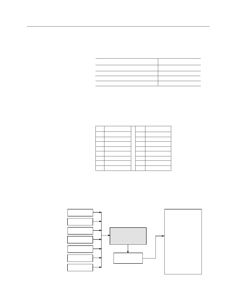
You cannot change the values shown in the Logic Status parameter
by directly acccessing the parameter. Instead, the Logic Status
parameter receives information from the logic evaluation block
(Fig. D.1).
Figure D.1
SCANport Interaction with Logic Status
SCANport 1
Logic Status
(Parameter 190)
Logic Evaluation
Block
SCANport 2
SCANport 3
SCANport 4
SCANport 5
SCANport 6
Terminal Block
Drive
Sequencing
Bit 0
Bit 1
Bit 2
Bit 3
Bit 4
Bit 5
Bit 6
Bit 7
Bit 8
Bit 9
Bit 10
Bit 11
Bit 12
Bit 13
Bit 14
Bit 15
Enabled
Running
Command Dir
Actual Dir
Accelerating
Decelerating
Alarm
Fault
At Speed
Local ID
Local ID
Local ID
Ref ID
Ref ID
Ref ID
Ref ID
Chapter Objectives
Logic Status Parameter