B013, Basic display group, Continued) – Rockwell Automation 22D PowerFlex 40P User Manual, FRN 3 User Manual
Page 51: B012 [control source, B013 [contrl in status, Programming and parameters 3-5
Programming and Parameters
3-5
Basic Display Group
(continued)
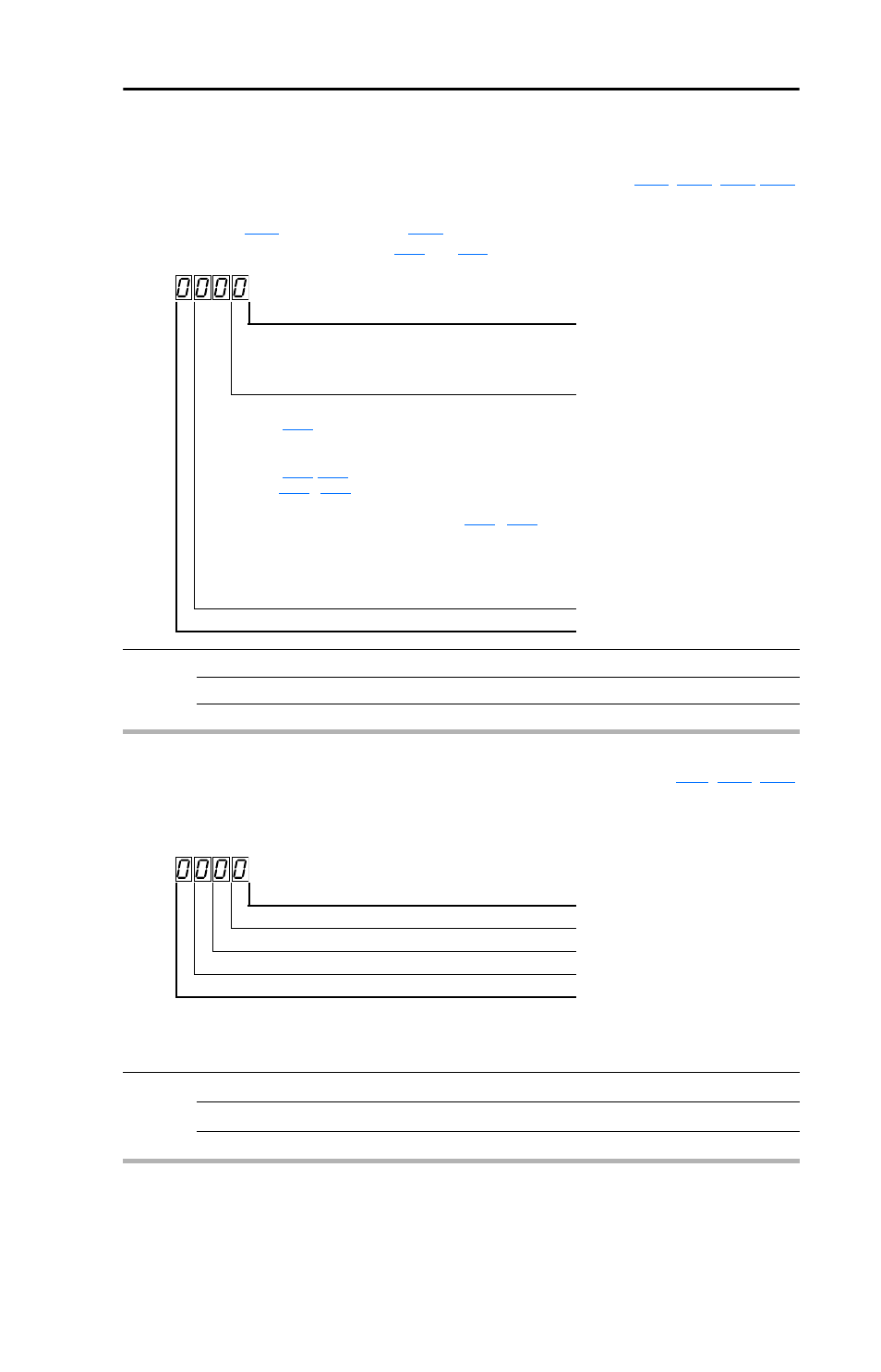
b012 [Control Source]
Related Parameter(s):
Displays the active source of the Start Command and Speed Command which are normally defined
by the settings of
[Start Source] and
[Speed Reference] but may be overridden by digital
inputs. Refer to the flowcharts on pages
and
for details.
Values
Default:
Read Only
Min/Max:
0/112
Display:
1
Start Command
Digit 1
1 = Terminal Block
2 = Communications
9 = Jogging
Speed Command
Digit 3 & 2
01 =
A069
[Internal Freq]
02 = 0-10V Input/Remote Potentiometer
03 = 4-20mA Input
04 =
-
[Preset Freq x]
(
[Digital Inx Sel] must be set to 4)
05 = RS485 (DSI) Port
06 = StepLogic Control (Parameters
-
07 = Analog Input Multiply
08 = PID Control
09 = Jogging
10 = Encoder or Pulse Train Reference
11 = Positioning Control
Reserved
Digit 4
b013 [Contrl In Status]
Related Parameter(s):
,
Status of the control terminal block control inputs.
Important: Actual control commands may come from a source other than the control terminal block.
Values
Default:
Read Only
Min/Max:
0/1
Display:
1
1 = Input Present, 0 = Input Not Present
Start / Run FWD Input (I/O Terminal 02)
Bit 0
Direction / Run REV Input (I/O Terminal 03)
Bit 1
Stop Input
(1)
(I/O Terminal 01)
Bit 2
(1)
The stop input must be present in order to start the drive.
When this bit is a 1 the drive can be started.
When this bit is a 0 the drive will stop.
Dynamic Brake Transistor On
Bit 3