Power terminal block, 12 installation/wiring, B frame c frame – Rockwell Automation 22D PowerFlex 40P User Manual, FRN 3 User Manual
Page 22
1-12
Installation/Wiring
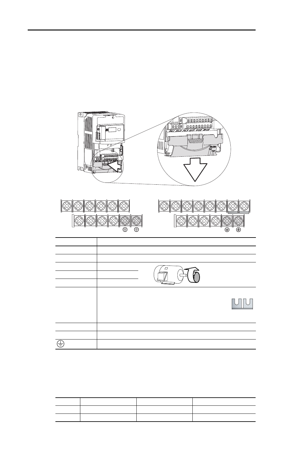
Power Terminal Block
The power terminal block is covered by a finger guard. To remove:
1. Press in and hold the locking tab.
2. Slide finger guard down and out.
Replace the finger guard when wiring is complete.
Figure 1.4 Power Terminal Block (Typical)
Table 1.E Power Terminal Block Specifications
Terminal
(1)
(1)
Important: Terminal screws may become loose during shipment. Ensure that all
terminal screws are tightened to the recommended torque before applying power to
the drive.
Description
R/L1, S/L2
1-Phase Input
(2)
(2)
Single-phase operation requires a 65% derate of drive rated current.
R/L1, S/L2, T/L3 3-Phase Input
U/T1
To Motor U/T1
=
Switch any two motor
leads to change
forward direction.
V/T2
To Motor V/T2
W/T3
To Motor W/T3
P2, P1
DC Bus Inductor Connection (C Frame drives only.)
The C Frame drive is shipped with a jumper between
Terminals P2 and P1. Remove this jumper only when a DC
Bus Inductor will be connected. Drive will not power up
without a jumper or inductor connected.
DC+, DC-
DC Bus Connection
BR+, BR-
Dynamic Brake Resistor Connection
Safety Ground - PE
Frame
Maximum Wire Size
(1)
(1)
Maximum/minimum sizes that the terminal block will accept - these are not
recommendations.
Minimum Wire Size
(1)
Torque
B
5.3 mm
2
(10 AWG)
1.3 mm
2
(16 AWG)
1.7-2.2 N-m (16-19 lb.-in.)
C
8.4 mm
2
(8 AWG)
1.3 mm
2
(16 AWG)
2.9-3.7 N-m (26-33 lb.-in.)
V/T2
T/L3
S/L2
R/L1
U/T1
W/T3
BR+
BR-
DC- DC+
V/T2
T/L3
S/L2
R/L1
U/T1
W/T3
P2
P1
BR+
BR-
DC- DC+
B Frame
C Frame