Trigger menu operation, Trigger icon overview – GW Instek GDS-200 Series User Manual User Manual
Page 66
GDS-200 & GDS-300 Series User Manual
66
Trigger Menu Operation
The Trigger menu controls the trigger position, trigger type and
trigger modes.
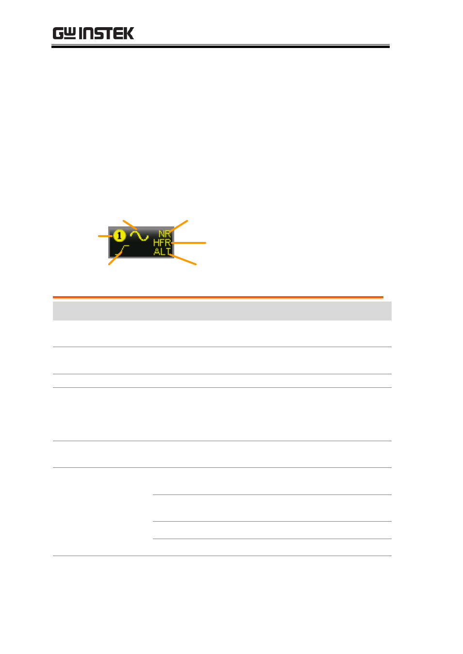
Trigger Icon Overview
The settings that have been set in the Trigger menu will be reflected
in the Trigger Menu Icon.
Trigger
source
Slope, polarity
or condition
Trigger
coupling
Noise
rejection
Alternate
trigger indicator
High/Low
frequency
rejection
Item
Description
Trigger Source
Shows the trigger source channel.
CH1, CH2
Trigger Coupling
Shows the trigger coupling.
AC Coupling, DC Coupling
Noise Rejection
Indicates that noise rejection is activated
Frequency
rejection
Indicates that high or low frequency rejection is
activated.
HFR = high frequency rejection
LFR = low frequency rejection
Alternate trigger
indicator
Indicates that the alternate trigger is activated.
Slope, polarity or
condition
This area will display the current trigger
conditions:
Edge
Rising slope, Falling slope, Either
slope
Pulse
Falling edge, Rising edge
Video
NTSC, PAL, SECAM