Micromod MOD: Modcell 2050R Users Guide User Manual
Page 137
IB-23C650
BASIC OPERATION
RESTART
Power up mode, set-point and output conditions can be defined so that at an
instrument power up condition the controller will assume these positions and
values. Power up data is stored in non-volatile memory and is read into the
operating memory at instrument power up. Controller mode at power up is
defined in the BASE CFG MENU and may be set at auto, manual, or last,
where last causes the controller to power up in the same mode as it was when
power was lost. Set-point source at power up is defined in the SETPTS
MENU and may be LOC, LO2, LO3, LO4, REM or fixed. The controller output
at power up is defined in the MA. OUTP MENU and may be last or fixed.
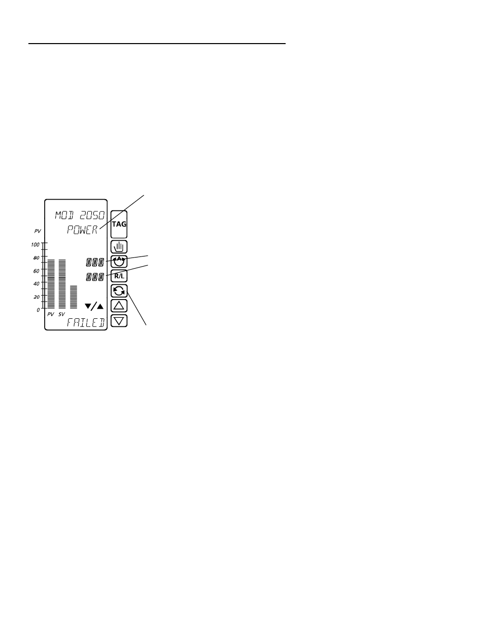
At power up, the instrument goes immediately to the DISPLAYS MENU, and
indicates a power failure.
If “hold power up” message located in
the BASE CFG menu has been
disabled, this message will only appear
briefly. Otherwise, press
SCRL
to
clear the message
.
If diagnostic
messages are present, they will show
next. See diagnostics section.
AUT, MAN
LOC, REM, LO2-LO4
Status displays will appear, as
configured prior to the last power down,
or defined for power up. Press the auto
key to change mode to auto, or the
manual key to change mode to manual.
Press the scroll key to display the
process and set-point variables. Press
again to see prompts for ramp/soak and
totalizer, if enabled.
131