Fig. 289: selecting an expanded map, Fig. 290: expanded map dialog box, Configuring ethernet/ip using rslogix5000 – Hardy HI 3010 Filler/Dispenser Controller User Manual
Page 97: Fig. 291: i/o configuration/adding a new module
83
Network
Installation
Step 37. Click on the Select button. Net Weight/Channel 2
(HFI9) appears in the Current Mappings field to the
right of the Hardy Control-Link Float Out selection
(EFO6) (See Fig. 287).
FIG. 287: CURRENT MAPPINGS/GROSS WEIGHT/
CHANNEL 2 (HFI9) ASSIGNED TO HARDY
CONTROL-LINK FLOAT OUT/WORD 4 (EFO4)
Step 38. Click on the Map button to map the assignment
statement. (See Fig. 288)
FIG. 288: GROSS WEIGHT ASSIGNED TO HARDY
CONTROL-LINK FLOAT OUT
Step 39. You can continue this process up to Item FO62.
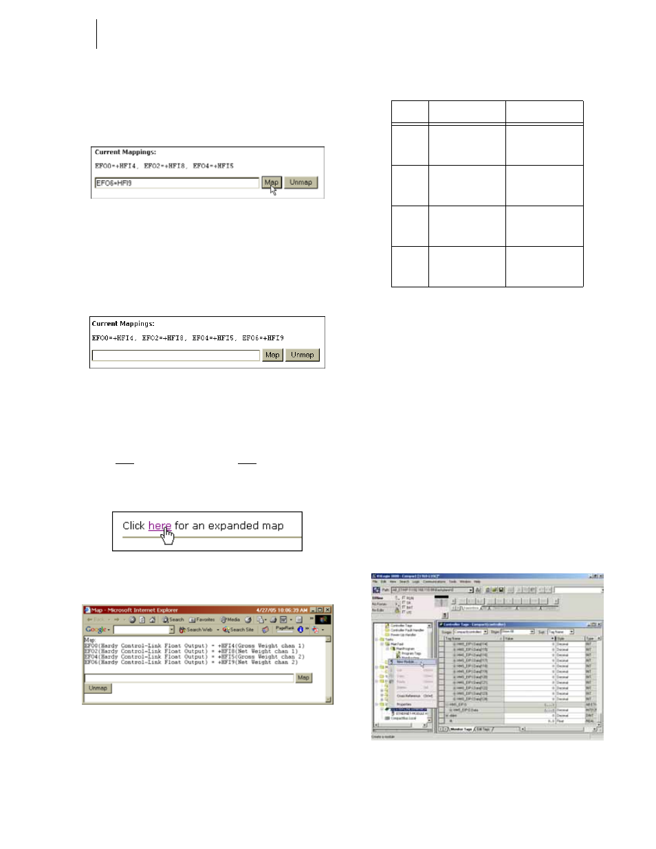
Step 40. To see what has been mapped click on the word
here in the statement “Click here for an expanded
map”. (See Fig. 289) The Expanded Map dialog
box appears. (See Fig. 290)
FIG. 289: SELECTING AN EXPANDED MAP
FIG. 290: EXPANDED MAP DIALOG BOX
•
Here is a table to show the mapping for the
OPC Server.
Configuring EtherNet/IP Using
RSLogix5000
®
These configurations procedures assume that
RSLogix5000
®
and ControlLogix5000
®
with an EtherNet/
IP™ module/bridge are set up and working correctly.
NOTE:
RSLogix5000® and ControlLogix5000® are reg-
istered trademarks of Rockwell Automation Inc.
NOTE:
The dip switches do not function. It is a good idea
to leave all of them in the OFF position.
Step 1. Create a new project or use an existing project and
set the program in “Offline” mode.
Step 2. Right click the EtherNet/IP module/bridge in the I/
O configuration. (See Fig. 291)
FIG. 291: I/O CONFIGURATION/ADDING A NEW
MODULE
Item #
Destination
Source
FO00
Hardy Control-
Link Float Output
- Word 0 (EFO0)
Gross Weight
Channel 1 (HFI4)
FO02
Hardy Control-
Link Float Output
- Word 2 (EFO2)
Net Weight Chan-
nel 1 (HFI8)
FO04
Hardy Control-
Link Float Output
- Word 4 (EFO4)
Gross Weight
Channel 2 (HFI5)
FO06
Hardy Control-
Link Float Output
- Word 6 (EFO6)
Net Weight Chan-
nel 2 (HFI9)