Removing the cord grip assembly, Installing the hi 3000-rc rear cover, Fig. 88: aligning the rear cover to the chassis – Hardy HI 3010 Filler/Dispenser Controller User Manual
Page 46: Cables in the cord grip assembly, The rear cover to the chassis
HI-3000 Series
32
Operation and Installation
FIG. 87: INSTALLING CABLES IN THE CORD GRIP
ASSEMBLY
NOTE:
When installing a BNC connector to the Control-
Net Option Card you must use a 90° elbow to
allow sufficient room to correctly route the cable.
Removing the Cord Grip Assembly
•
Use a box end wrench to hold the cord grip
assembly nut so that it doesn’t move when
loosening the Hex Nut.
•
Use a box end wrench to remove the Hex
Nut.
•
Slide the Cord Grip out of the rear cover.
•
For further disassembly you can use a box
end wrench and remove the Cord Grip
Nut, although it is not necessary for
removal.
•
Install a NEMA 4 plug.
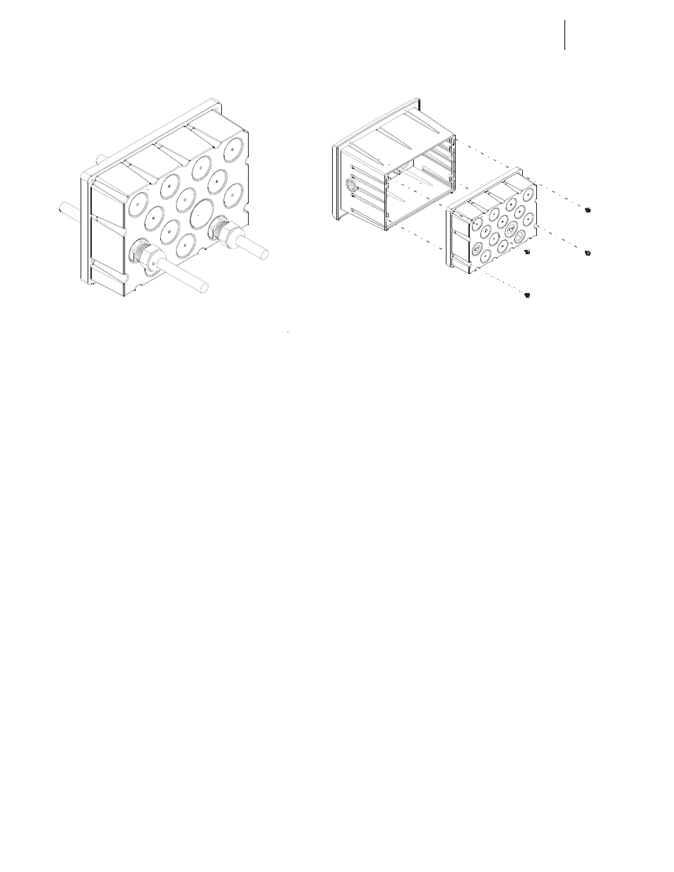
Installing the HI 3000-RC Rear Cover
Step 1. Check to see that all the Cable Grips and Cables are
installed.
Step 2. Install the wires into the cord grips in the rear panel.
Step 3. Connect the wires to the connectors on the rear
panel of the HI 3000 instrument.
Step 4. Position the rear cover, pulling the cable if neces-
sary so that the thru holes on the rear cover align
with the threaded holes on the HI 3000 Instrument
chassis. (See Fig. 88)
FIG. 88: ALIGNING THE REAR COVER TO THE
CHASSIS
Step 5. Place the rear cover onto the rear of the Chassis.
Step 6. Use a phillips head screw driver and screw the four
(4) screws into the threaded holes on the rear panel
of the chassis.
Step 7. Tighten the screws until they are snug. There is a
gasket installed in the rear cover which needs to be
slightly depressed to provide a NEMA 4X seal.
CAUTION: D
O
NOT
OVERTIGHTEN
. O
VERTIGHTENING
MAY
DAMAGE
THE
REAR
COVER
OR
THE
INSTRUMENT
.
Step 8. Use a box end wrench and tighten the Cord Grip
Assembly Nut until the cables when tugged do not
come out of the Cord Grip. (See Fig. 89)
Step 9. Install the NEMA 4 plugs in empty holes if neces-
sary. (See Fig. 89)