Profibus-dp network setup, Fig. 139: profibus logo, Initialization process – Hardy HI 3010 Filler/Dispenser Controller User Manual
Page 63: Profibus-dp .gsd file, Pre-initialization procedures, Profibus-dp network setup initialization process, Iguration - options/selecting view, E profibus network with trunk and drop lines - 49
49
Network
Installation
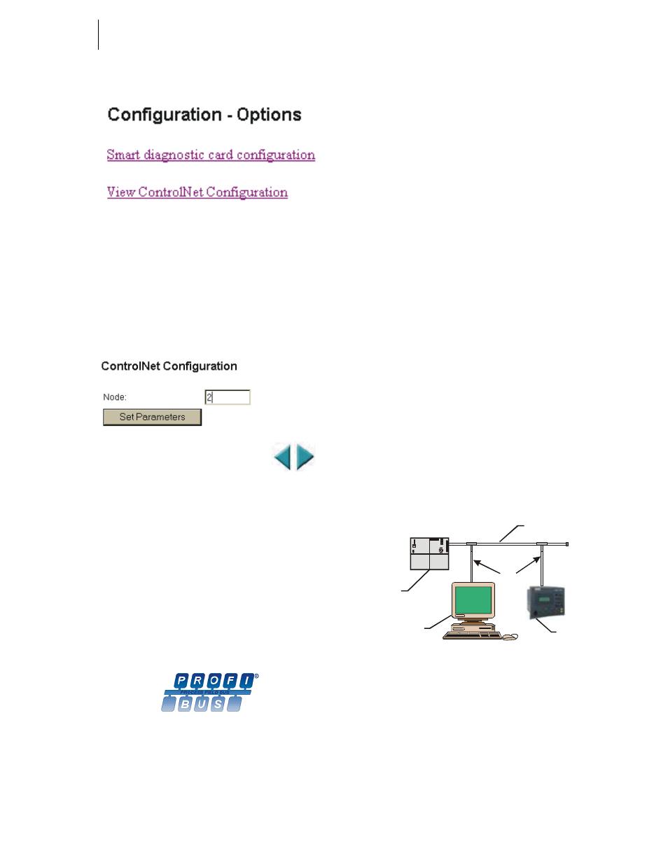
FIG. 137: CONFIGURATION - OPTIONS/SELECTING
VIEW CONTROLNET CONFIGURATION OPTION
Step 3. Click on View ControlNet Configuration. (See Fig.
137) The ControlNet Configuration Page appears.
(See Fig. 138)
FIG. 138: CONTROLNET CONFIGURATION PAGE/
SELECTING THE NODE ADDRESS
Step 4. Double Click in the Node: Text field. (See Fig. 138)
Enter the node address of this HI 3000 instrument.
(Node Address Range: 0-99)
Step 5. Click on Set Parameters. The Node address is set
for this instrument.
PROFIBUS-DP Network Setup
FIG. 139: PROFIBUS LOGO
NOTE:
Hardy Process Solutions is a member of Profibus
International.
Initialization Process
To be able to add an HI 3000 Series Instrument to a Profibus-
DP network, you need a PC and software such as Siemens
Step 7™, Simatic Manager or equal, that allows the Profi-
bus-DP PLC and the HI 3000 Series Instrument to exchange
data. Profibus Specifications are located in the Installation
and Service Manual for each HI 3000 Series Instrument.
Profibus-DP .GSD File
All devices connected to a Profibus-DP network requires a
*.gsd file. The *.gsd file contains all the parameters includ-
ing the baud rate, table formats and necessary data required
by the network PLC when an HI 3000 Series Instrument is
connected to the network.
A copy of the *.gsd file can be found on the CD that comes
with the instrument or at the Hardy Website or at http://
www.profibus.com/libraries.html.
Whichever Simatic Manager you select, you must go
through these three steps:
Step 1. Connect the HI 3000 Series Instrument to the Profi-
bus DP network and verify the address. (See Fig.
140) (Installation and Cabling Instructions are
located in the Cabling Section of this Manual)
Step 2. Connect the PC to the Trunk Line. Load the config-
uration properties to the initialization software on
the PC and transfer them to the PLC.
Step 3. Install the *.gsd file, and map I/O data table proper-
ties to the instrument.
FIG. 140: SIMPLE PROFIBUS NETWORK WITH
TRUNK AND DROP LINES
Pre-Initialization Procedures
Step 1. Inspect the network cables and make sure that the
cables have been installed correctly and satisfy the
Profibus-DP guidelines for the data transmission
baud rate(s) required. (See the Cabling Chapter/
Profibus Installation in this manual for Profibus-DP
cable specifications and cabling guidelines.)
24VDC
VOLTAGE
SELECTOR
RUN-P
RUN
STOP
MRES
SF
B ATF
D C5V
D C5V
FR CE
R UN
ST OP
C PU 315 -2 DP
SI EME NS
SIMATIC
Personal
Computer
Siemens
PLC
HI 3000
Series Instrument
Trunk Line
Drop Lines