Fig. 163: modbus - options/enabled, Installing hardy modbus-link, Fig. 164: hardy modbus-link display – Hardy HI 3010 Filler/Dispenser Controller User Manual
Page 70: Fig. 165: hardy modbus-link/selecting connect, Odbus - options/enabled, Ardy modbus-link display, Ardy modbus-link/selecting connect
HI-3000 Series
56
Operation and Installation
Step 8. Click on the Set Parameter button.
Step 9. This procedure activates the Modbus option on in
the instrument.
Step 10. The HI 3000 module is Modbus enabled. (See Fig.
163)
FIG. 163: MODBUS - OPTIONS/ENABLED]
Step 11. You can now map from your client (PLC) to the HI
3000 module via Modbus.
Installing Hardy Modbus-Link
If you do not have a PLC or other client, Hardy has provided
the Hardy Modbus-Link Client to communicate with the HI
3000 module. For the sake of clarity the Client/Server defini-
tions are as follows:
•
Client - The module asking for data.
•
Server - The module providing the data.
The Hardy Modbus-Link will not work without the key. To
purchase the Modbus Option with the key, contact your local
Hardy Instruments Representative or Hardy Instruments,
Customer Service.
Step 1. On the Documentation CD you received with your
HI 3000 Instrument you will find a copy of the
Hardy Modbus-Link Software. If you do not have
the CD that came with your instrument you can go
to the HI 3000 Resources Web page and download
the application from there.
Step 2. Double click on the Hardy Modbus-Link .exe file to
install the software on your PC. Once the Installa-
tion is complete a Hardy Modbus-Link icon appears
on your Desktop.
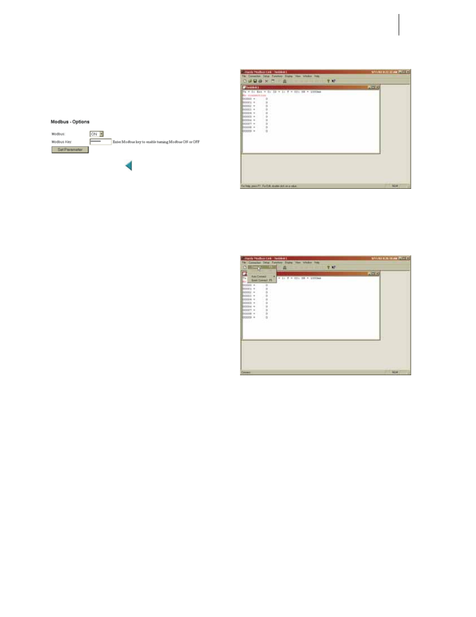
Step 3. Double click the Hardy Modbus-Link icon. The
Hardy Modbus-Link display appears. (See Fig.
164)
FIG. 164: HARDY MODBUS-LINK DISPLAY
Step 4. Click on the Connection pull down menu. (See Fig.
165)
FIG. 165: HARDY MODBUS-LINK/SELECTING
CONNECT
Step 5. Click on “Connect”, the TCP/IP Connection display
appears. (See Fig. 166)
•
If TCP/IP is not selected, click on the pull
down list and select it. (See Fig. 167)