Fig. 22: dry contact wiring diagram, Output relay wiring, Load point connections – Hardy HI 3010 Filler/Dispenser Controller User Manual
Page 26: Fig. 23: rear panel/load point connections, C2® load point connection, Non-c2 load cell connection, Rs 232 connection, Output relay wiring load point connections, Non-c2 load cell connection rs 232 connection, Ry contact wiring diagram
HI-3000 Series
12
Operation and Installation
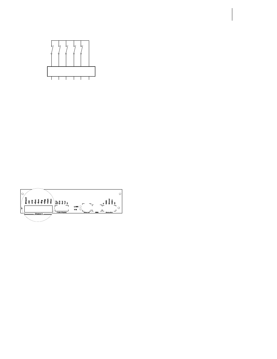
FIG. 22: DRY CONTACT WIRING DIAGRAM
Step 3. Go to the product service manuals (Chapter 6) for
instructions on how to map to the digital inputs.
Output Relay Wiring
The HI 3000 Series has 4, OPTO22 solid state relays. Please
see Relays in Chapter 2 - Specifications of each product Ser-
vice manual for details.
Step 1. Wire into the output relay of your choice.
Step 2. Go to the product service manuals (Chapter 6) for
instructions on how to map to the output relays.
Load Point Connections
FIG. 23: REAR PANEL/LOAD POINT CONNEC-
TIONS
C2
®
Load Point Connection
WARNING: L
OAD
CELL
CABLE
LENGTH
HAS
BEEN
CAL
-
CULATED
INTO
C2
CALIBRATION
DATA
. H
ARDY
P
ROCESS
S
OLUTIONS
RECOMMENDS
THAT
YOU
DO
NOT
CUT
YOUR
A
DVANTAGE
OR
A
DVANTAGE
L
ITE
LOAD
SENSOR
CABLE
,
AS
YOUR
C2
ACCURACY
WILL
BE
AFFECTED
AND
THE
WARRANTY
WILL
BE
VOIDED
.
Cable color Code for C2 Load Points (left to right facing the
rear panel):
•
Shield
Ground Wire
•
C2-
Violet
•
C2+
Grey
•
EXC-
Black
•
SEN-
Brown
•
SIG-
White
•
SIG+
Green
•
SEN+
BLUE
•
EXC+
RED
Step 1. Remove the factory installed jumper from the ter-
minal block if you are connecting an 8 wire cable
from the junction box.
Step 2. Connect the cable (Recommended load cell cable:
Hardy Instruments Prt. # 6020-0001) wires to the
Channel 1 terminal block according to the cable
color chart.
NOTE:
To purchase Hardy Load Cell cable, contact your
local Hardy Representative or Distributor.
Step 3. Plug the terminal block into the Channel connector
on the rear panel.
Step 4. For more information concerning C2 Load Point
connections, consult the individual HI 3000 Series
Product, Installation and Service Manual.
Non-C2 Load Cell Connection
Cable color Code using Hardy cable from a junction to an
instrument - for Non-C2 load cells:
•
Shield
Ground Wire
•
C2-
Not Used
•
C2+
Not Used
•
EXC-
Black
•
SEN-
Brown
•
SIG-
White
•
SIG+
Green
•
SEN+
Blue
•
EXC+
Red
Step 1. Remove the factory installed jumper from the ter-
minal block if you have 6 wire load cell cable that
includes sense wires from the load cell or junction
box.
Step 2. Connect the cable (Recommended load cell cable:
Hardy Prt. # 6020-0001) wires to the J9 terminal
block according to the Non-C2 cable color chart.
Step 3. Plug the terminal block into the Channel 1 (J9) con-
nector on the rear panel.
Step 4. For more information concerning Non-C2 Load
Point connections, consult the HI 3000 Series
Installation and Service Manual.
RS 232 Connection
The RS 232 Connection provides for a serial port for trans-
mission to a Printer or a Scoreboard. To configure the Printer
or Scoreboard see Chapter 4/Serial Port Parameters in the HI
3030 Service Manual.
Gnd
1 2 3 4
5