Led status indicators, Ethernet/ip™ option card installation, Ontrolnet configuration/entering node – Hardy HI 3010 Filler/Dispenser Controller User Manual
Page 36
HI-3000 Series
22
Operation and Installation
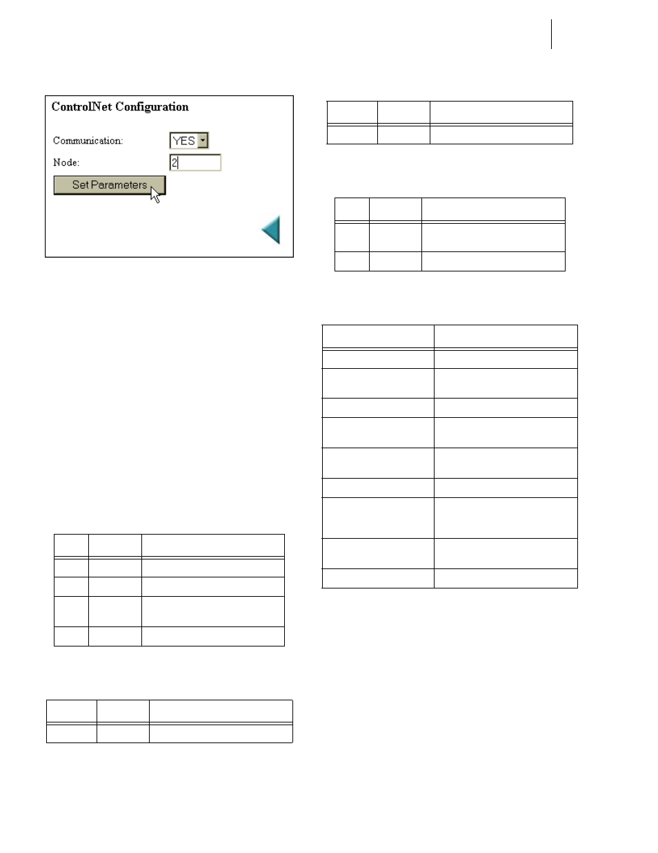
FIG. 62: CONTROLNET CONFIGURATION/ENTER-
ING NODE ADDRESS
Step 8. Click on the Set Parameters button to save the set-
tings.
Step 9. Click on the left arrow or the word “home” at the
bottom of the page to return to the Home Page.
LED Status Indicators
The ControlNet Card is fitted with four bi-color status and
indicator LED’s. (See Fig. 88) During startup the Module
Status (LED 1) and the Module Owned (LED 4) are red for
one (1) second to indicate they are working properly. After
the one second period they are lit as specified below in the
tables. After the module is initialized, the network LED’s
will flash red/green for one (1) second, indicating a self test
of the network chip.
For information on setting up the module using RSLogix
5000 and RSNetworx go to the Network Section of this man-
ual.
EtherNet/IP™ Option Card Installation
CAUTION: M
AKE
SURE
THAT
YOU
USE
AN
ANTI
-
STATIC
STRAP
WHEN
INSTALLING
THE
E
THER
N
ET
/IP O
PTION
C
ARD
.
NOTE:
The dip switches do not function. It is a good idea
to leave all of them in the OFF position. Should
you accidentally turn on a dip switch nothing will
happen. The IP address is configured by the firm-
Color
Frequency
Description
Green
Flashing
Module is waiting for initialisation
Green
Steady on
Module is initialized
Red
Flashing
Minor fault, MacID has been changed
after initialisation, etc.
Red
Steady on
Major fault, module must be restarted
TABLE 4: LED 1 - MODULE STATUS
Color
Frequency
Description
Red/Green
-
See Table 5
TABLE 5: LED 2 - LED CHANNEL A
Color
Frequency
Description
Red/Green
-
See Table 5
TABLE 6: LED 3 - LED CHANNEL B
Color
Frequency
Description
Green
Steady on
A connection is opened against the
ControlNet Module
Off
-
No connection is opened
TABLE 7: LED 4 - MODULE OWNED
Channel LED’s
Description
A & B, steady off
Module is not initialized
A & B, steady red
Faulted unit, must be restarted or
repaired
A & B, alternating red/green
Selftest of bus controller
A&B, flashing red
Incorrect node configuration, dupli-
cate MacID, etc.
A or B, steady off
Channel is disabled, depending on
network configuration
A or B, steady green
Normal operation of channel
A or B, flashing green
Temporary errors (node will self cor-
rect) or node is not configured to go
online
A or B, flashing red
Media fault or no other nodes on the
network
A or B, flashing red/green
Incorrect network configuration
TABLE 8: CHANNEL LED’S