Fig. 78: analog output option 2an, Electrical connection, Fig. 80: analog electrical connections – Hardy HI 3010 Filler/Dispenser Controller User Manual
Page 43: Removing the analog option card, Rear cover installation (hi 3000-rc), Alog output option 2an, The analog option card in a 3000 chassis - 29, Alog electrical connections
29
Cabling
Installation
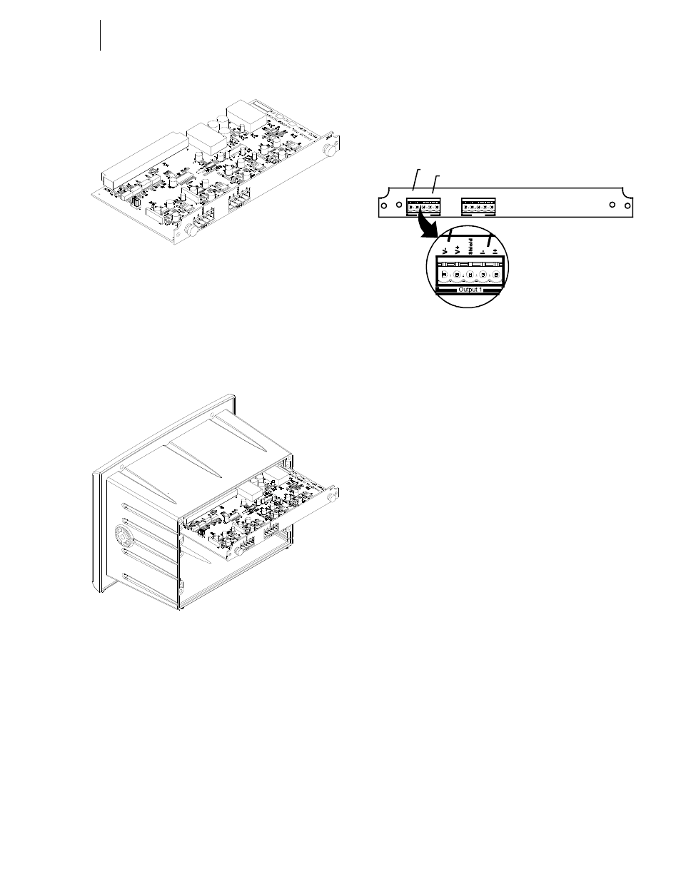
FIG. 78: ANALOG OUTPUT OPTION 2AN
NOTE:
You can only use Option Slot #1 if either the RIO
Option or the ControlNet Option cards are
installed.
Step 2. Slide the Analog Option Card into Slot #0 or Slot
#1. (See Fig. 79)
FIG. 79: INSTALLING THE ANALOG OPTION CARD
IN A 3000 CHASSIS
Step 3. Push the Analog card up against the back plane and
gently press until the card connector seats in the
back plane connector.
Step 4. Use a phillips head screw driver and install the two
(2) screws that fasten the Analog card panel to the
HI 3000 Instrument Chassis.
Step 5. Tighten the screws until the Analog panel is snug.
Do not overtighten.
NOTE:
If you want 4 Analog outputs, install 2 Analog
Output Option cards, one in Option Slot #0 and
one in Option Slot #1.
Electrical Connection
Step 1. If you are using a current output (4-20 milliamp)
connect the positive and negatives wires to the -I
and +I pins. (See Fig. 80)
FIG. 80: ANALOG ELECTRICAL CONNECTIONS
Step 2. If you are using a voltage output (0-10 Volts) con-
nect the positive and negative voltage wires to the (-
V and +V pins).
Step 3. Connect ground to the Shield pin.
CAUTION: D
O
NOT
CONNECT
BOTH
V
OLTAGE
AND
C
UR
-
RENT
TO
ONE
OUTPUT
CONNECTOR
. I
F
YOU
WANT
V
OLT
-
AGE
AND
C
URRENT
O
UTPUT
IN
THE
SAME
INSTRUMENT
YOU
MUST
WIRE
THEM
TO
SEPARATE
OUTPUT
CONNEC
-
TORS
.
Removing the Analog Option Card
Step 1. Disconnect the connector from the terminal block.
Step 2. Use a phillips head screw driver and remove the
two (2) screws that fasten the Analog Option Card
panel to the HI 3000 Chassis.
Step 3. Using the thumb and index finger on both hands,
grasp the two (2) knobs on the card panel and pull
away from the instrument.
Step 4. When the Analog Option Card clears the chassis,
store in a static free, safe location.
NOTE:
For Configuration and Mapping instructions see
the individual HI 3000 product Technical manu-
als, Configuration Section (Chapter 4). The
installation for all HI 3000 Series instruments is
the same.
Rear Cover Installation (HI 3000-RC)
Rear cap for the HI 3000 Series controllers. Upgrades the
entire assembly to a NEMA 4X rating by enclosing all the
rear panel connectors. (See Fig. 123) You will need to install
the Cable Grip Assemblies and cabling before installing the
Rear Cover.
Sh
ield
V-
V+
I-
I+
Output 1
Output 2
Sh
ield
V-
V+
I-
I+
2AN
Voltage
Current