Fig. 108: saving the configuration, Using the ping tool, Assigned to node 0 through node 7 – Hardy HI 3010 Filler/Dispenser Controller User Manual
Page 54: Configuration, Node configuration from
HI-3000 Series
40
Operation and Installation
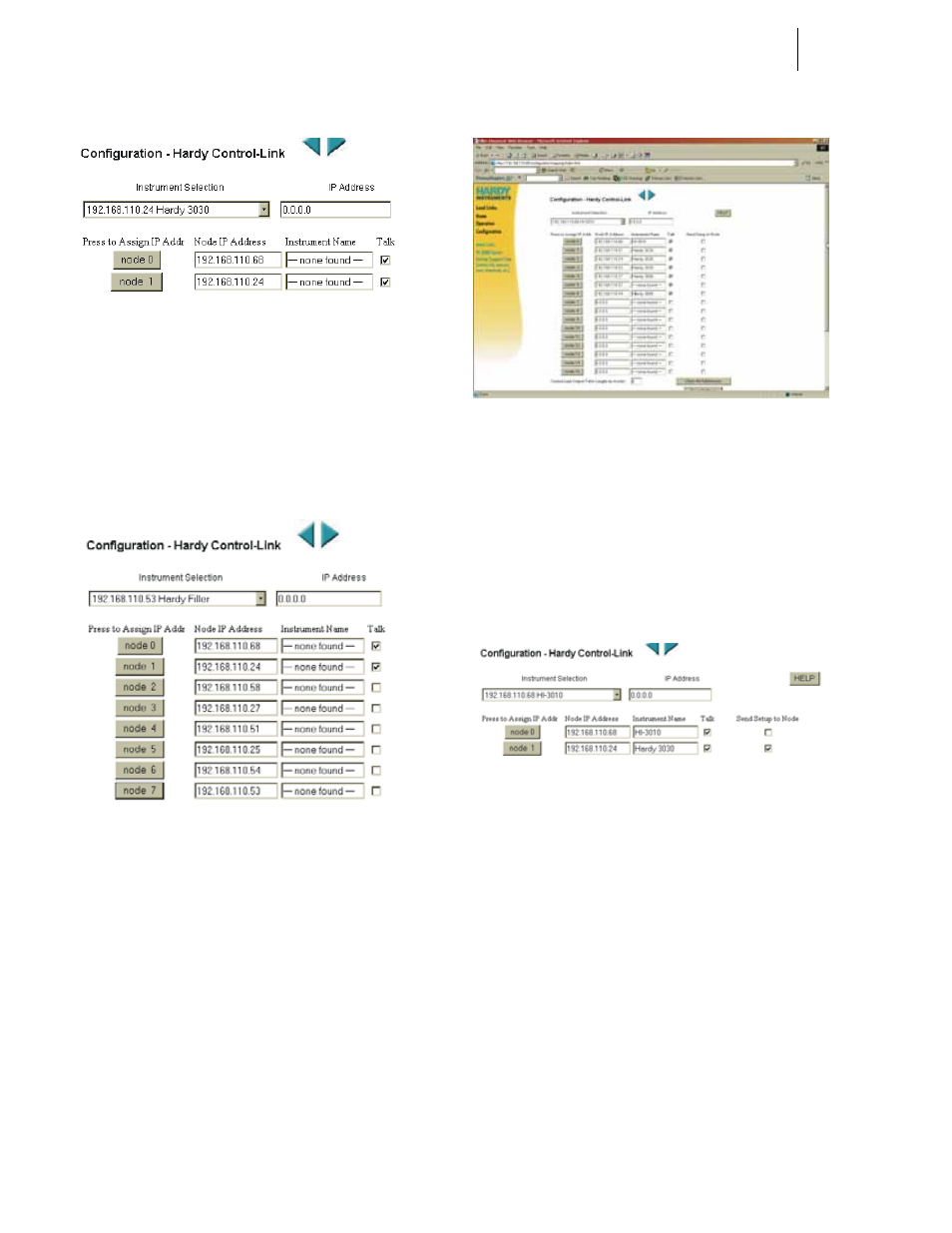
FIG. 106: HI-3010 (IP ADDRESS 192.168.110.24)
ASSIGNED TO NODE 1
Step 8. Continue assigning instruments to the node
addresses until all the instruments you want in the
table are assigned. (See Fig. 107)
Step 9. Now click in the Talk check boxes to allow the
instruments to communicate with each other. (See
Fig. 107)
FIG. 107: INSTRUMENTS ASSIGNED TO NODE 0
THROUGH NODE 7
Step 10. Click on the Save Settings button to save the con-
figuration. (See Fig. 108)
FIG. 108: SAVING THE CONFIGURATION
Step 11. This is an optional procedure but highly recom-
mended. If you want to transfer an exact copy of the
node 0 setup to another node, click in the “Send
Setup to Node” check box of the node you want to
receive the setup of Node 0. (See Fig. 109) In our
example we sent the setup to node 1.
Step 12. Click on the Save Settings button to complete the
transfer.
FIG. 109: TRANSFERRING THE NODE
CONFIGURATION FROM NODE 0 TO NODE 1
NOTE:
It is a good idea to have the same node setup on
every HI 3000 Series Instrument on your Hardy
Control-Link Network.
Using the Ping Tool
To troubleshoot the network and instrument configuration go
to Chapter 7 - Troubleshooting in the HI 3000 Series Instru-
ment Service Manual.