Led status indicators, Fig. 73: connector/dip switches/leds, Led 1 - link (activity) – Hardy HI 3010 Filler/Dispenser Controller User Manual
Page 39: Led 2 - module status, Led 1 - link (activity) led 2 - module status, Age/selecting view ethernet/ip, Onnector/dip switches/leds
25
Cabling
Installation
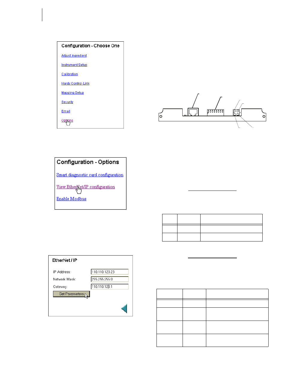
FIG. 70: CONFIGURATION PAGE/SELECTING
OPTIONS
FIG. 71: OPTIONS PAGE/SELECTING VIEW ETH-
ERNET/IP CONFIGURATION
Step 4. Click on View EtherNet/IP configuration. (See Fig.
113) The EtherNet/IP page appears. (See Fig. 72)
FIG. 72: ETHERNET/IP PAGE/SETTING IP
ADDRESS
Step 5. Click in the IP Address text field. Delete the current
IP Address.
Step 6. Type in the new IP address.
Step 7. If necessary repeat steps 6 & 7 for the Network
Mask and Gateway.
Step 8. Click on the Set Parameters button to save the
parameters.
Step 9. Click on the left arrow or the word “home” at the
bottom of the page to return to the Home Page.
LED Status Indicators
FIG. 73: CONNECTOR/DIP SWITCHES/LEDS
The Ethernet/IP Card is fitted with four bi-color status and
indicator LED’s. (See Fig. 115) During startup the Module
Status (LED 2) and Network Status (LED 3) are red for one
(1) second to indicate they are working properly. After the
one second period they are lit as specified below in the
tables. The HI 3000 Series products use the default settings.
LED 1 - Link (Activity)
•
LED 1 Configuration
LED 2 - Module Status
•
LED 2 Configuration
Color
State
Indicates:
Green
Steady On
Module has a link
Green
Steady Off
Module does not sense a link
TABLE 9: LED 1 - MODULE STATUS/CONFIGURATION
State
Summary
Description
Steady Off
No Power
No power applied to the module
Steady Green
Device
Operational
The module is operating properly
Flashing
Green
Standby
The module has not been configured
Flashing Red
Minor Fault
A minor recoverable fault has been
detected
TABLE 10: LED 2 CONFIGURATION
1 2 3 4 5 6 7 8
ON
RJ 45
Connector
Dip
Switches
LED 1
LED 2
LED 4
LED 3