Led 3 - network status, Led 4 - activity, Profibus option card installation – Hardy HI 3010 Filler/Dispenser Controller User Manual
Page 40: Profibus connection and setup, Hardware requirements, Software requirements, Cabling guidelines, Led 3 - network status led 4 - activity, Hardware requirements: software requirements, Ofibus db9 serial connector with slide
HI-3000 Series
26
Operation and Installation
LED 3 - Network Status
•
LED 3 Configuration
LED 4 - Activity
•
LED 4 Configuration - This LED flashes
green each time a packet is received or
transmitted.
Profibus Option Card Installation
CAUTION: M
AKE
SURE
THAT
YOU
USE
AN
ANTI
-
STATIC
STRAP
WHEN
INSTALLING
THE
P
ROFIBUS
O
PTION
C
ARD
.
Step 1. Position the Profibus Option Card with the back
plane connector facing Option Slot #0.
NOTE:
You can only use Option Slot #0 when installing
the Profibus.
Step 2. Slide the Profibus Option Card into Slot #0.
Step 3. Push the Profibus card up against the back plane
and gently press until the card connector seats in the
back plane connector.
Step 4. Use a phillips head screw driver and install the two
(2) screws that fasten the Profibus card panel to the
HI 3000 Instrument Chassis.
Step 5. Tighten the screws until the Profibus panel is snug.
Do not overtighten.
Profibus Connection and Setup
Hardware Requirements:
•
Hardy Profibus Option Card
•
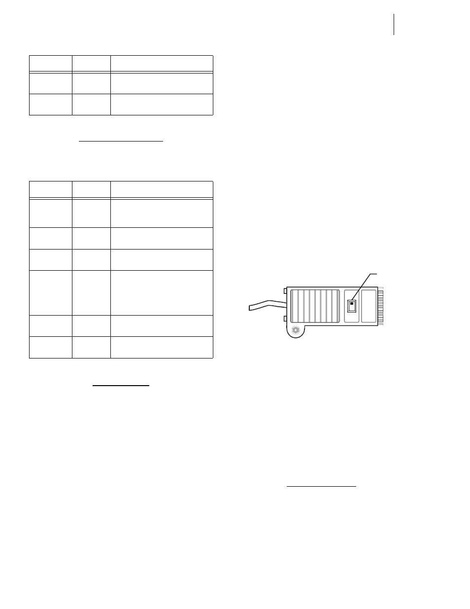
Profibus Cable with DB9 Serial Connec-
tors on both ends. It is recommended that
you use a Serial Connector with a slide
switch to terminate an instrument that is
located at the end of a Fieldbus (Profibus)
Network. (See Fig. 74)
NOTE:
The Profibus-DP cable must conform to the
PROFIBUS-DP EN 50 170 Specification for
Cable.
FIG. 74: PROFIBUS DB9 SERIAL CONNECTOR
WITH SLIDE SWITCH/MALE
Software Requirements:
•
Siemens Step 7™, Simatic Manager or
equivalent.
•
Hardy *.GSD File (Available on the HI
3000 CD or current.GSD file can be down-
loaded from the Hardy Website (http://
www.hardyinst.com) or the Profibus Web
Site (http://www.profibus.com/librar-
ies.html)
Cabling Guidelines
1.
The Trunk Line is the main network cable and anchors
the two ends of the network.
2.
A Drop Line is the network branch cable between the
trunk line tap or junction box and the HI 3000 Series
instrument. The baud rate selection can affect and/or
restrict each of the following variables:
Steady Red
Major Fault
A major internal error has been
detected
Flashing
Green/Red
Self-Test
The module is performing a power on
self test
State
Summary
Description
Steady Off
No Power
or no IP
address
The module has no power or no IP
address has been assigned
Steady Green
Connected
The module has at least on estab-
lished EtherNet/IP connection
Flashing
Green
No Con-
nections
There are no EtherNet/IP connections
established to the module
Flashing Red
Connec-
tion Time-
out
One of more of the connections in
which this module is the target has
timed out. This state is only left if all
timed out connections are re-estab-
lished or if the module is reset.
Steady Red
Duplicate
IP
The module has detected that its IP
address is already in use
Flashing
Green/Red
Self-Test
The module is performing a power on
self test
TABLE 11: LED 3 CONFIGURATION
State
Summary
Description
TABLE 10: LED 2 CONFIGURATION
ON
OF
F
S
IEM
EN
S
Slide
Switch