Network: installation, About networks, Simple ethernet network (see fig. 90) – Hardy HI 3010 Filler/Dispenser Controller User Manual
Page 49: Materials required, Fig. 90: simple hardy control-link network, Fig. 91: ip address configuration, Network, About networks simple ethernet network, Hardy control-link network, Configuration
35
Network
Installation
NETWORK: INSTALLATION
About Networks
The HI 3000 Series Network configurations include:
•
Hardy Control-Link (Ethernet 10/100
Base T)
•
DeviceNet
•
ControlNet
•
Profibus DP
•
Ethernet/IP
•
Modbus TCP/IP
This enables the HI 3000 Series to communicate with virtu-
ally every device on the network, including PCs and PLCs.
This means that you can map, configure and monitor all the
HI 3000 series products from the front panel or your LAN,
Internet, DeviceNet, ControlNet and Wireless Servers that
are connected to the Network.
Simple Ethernet Network (See Fig. 90)
Materials Required
•
Ethernet Card for your LapTop.
•
Ethernet Crossover Cable with RJ45 Con-
nectors on both ends.
•
Browser on your Lap Top.
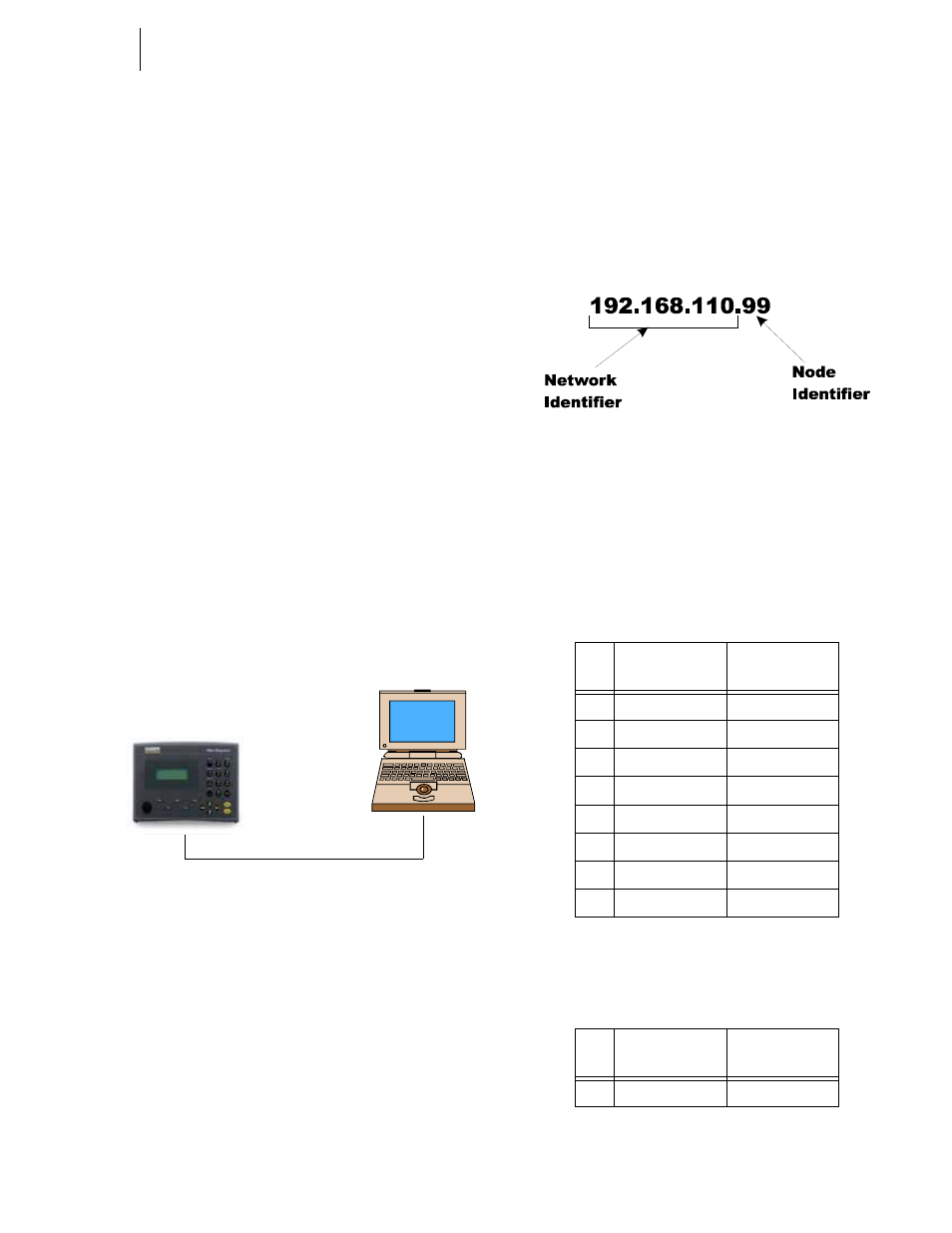
FIG. 90: SIMPLE HARDY CONTROL-LINK
NETWORK
Step 1. Contact your Network Administrator for the IP
address of the instrument you want to connect to. If
the Instrument does not have an IP address, create
one. (See Cabling: Installation/Ethernet Cable Con-
nection and Setup Section in this manual)
NOTE:
To connect to the HI 3000 instrument requires
that your laptop IP address be in the same Class
and the same Network Segment. For example if
the IP address of the instrument is 192.168.110.x
you will have to create an IP address for your
laptop that includes the first three octets. An octet
consists of a 3 digit number between 0 and 255.
An IP address consists of 4 octets. The first three
(3) octets identify the network. The 4th octet is
the identifier for the individual node. (See Fig.
91)
FIG. 91: IP ADDRESS CONFIGURATION
Step 2. Connect one of the RJ45 Connectors to the Ethernet
connection at the rear panel of the HI 3000 Series
products.
Step 3. Connect the other RJ45 Connector to the Ethernet
connection on your Laptop Ethernet card or your
Ethernet Adapter. The 10BaseT Cable pinouts are
as follows:
Pin
Colors on one
side of Cable
Colors on other
end of Cable
1
Orange/White
Orange/White
2
White/Orange
White/Orange
3
Green/White
Green/White
4
White/Blue
White/Blue
5
Blue/White
Blue/white
6
White/Green
White/Green
7
Brown/White
Brown/white
8
White/Brown
White/Brown
TABLE 17: PINOUTS FOR 10BASE T STANDARD
CABLE
Pin
Colors on one
side of Cable
Colors on other
end of Cable
1
White/Orange
White/Green
TABLE 18: PINOUTS FOR 10BASE T CROSSOVER
CABLE