Cable specification, B9 connector on the hardy profibus option card, Tting node address to 0, 0 – Hardy HI 3010 Filler/Dispenser Controller User Manual
Page 41
27
Cabling
Installation
NOTE:
A trade off between the longest length of Trunk
and Drop cable that can be used and the selected
data transfer speed. Baud rate selection
•
The available number of network nodes.
•
The total overall length of the Trunk Line.
•
The type of cable used for the Trunk Line.
•
The sum total length of all individual drop
lines.
Cable Specification
The specifications for Profibus standard Type A cable are
provided in Table 8. This type of cable is recommended for
transmission speeds above 500k baud, and any long distance
installations.
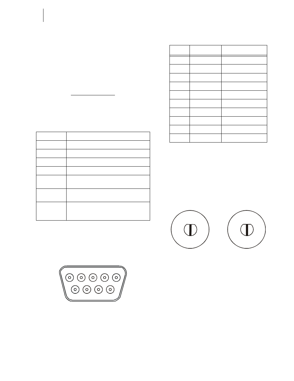
Step 1. Connect the Profibus cable connectors to the DB9
female serial connector on the Profibus Option
Card. (See Fig. 75)
FIG. 75: DB9 CONNECTOR ON THE HARDY PROFI-
BUS OPTION CARD
Step 2. Use a slotted head screw driver and configure the
Node address of the Instrument by setting the flats
of the rotary switches so that they are pointing to
zero (0,0). (See Fig. 76)
NOTE:
Changing the rotary switches to an address other
than 0, 0 - Profibus will not work. (See Fig. 76)
FIG. 76: ROTARY SWITCHES/SETTING NODE
ADDRESS TO 0, 0
Impedance
35 up to 165 ohm at frequencies from 3 to 20 Mhz
Cable Capacity
<30 pF per meter
Cable Diameter
>0.34 mm2, corresponds to AWG 22
Cable Type
Twisted pair cable, 1x2 or 2x2 or 1x4 lines.
Resistance
<110 ohm per km
Signal
Attenuation
max 9dB over total length of line section
Shielding
CU shielding braid or shielding braid and shield-
ing foil.
Max Bus
Length
200 m at 1500 kbit/second; up to 1.2 km at 93.75
kbit/second. Maximum length may be extended
with installation of repeater devices.
TABLE 12:
5
1
9
6
Female Connector on the
Hardy Profibus Option Card
Pin
Name
Function
Housing
Shield
Connected to PE
1
Not Connected
-
2
Not Connected
-
3
B-Line
Non-inverting RxD/TxD
4
RTS
Request to send
5
GND BUS
GND from RS485
6
+5 V BUS
+5 V from RS485
7
Not Connected
-
8
A-Line
Inverting RxD/TxD
9
Not Connected
-
TABLE 13: 9-PIN DSUB CONNECTOR
O 1
2
3
4 5
6
7
8
9
O 1
2
3
4 5
6
7
8
9
x 10
x 1