Monitoring weighing parameters, Short glossary of terms, Tare value – Hardy HI 3010 Filler/Dispenser Controller User Manual
Page 18: About cable termination, Dip switch settings, Installing the rio option board, Fig. 4: remote i/o option card, Minating switch for terminating last module, Emote i/o option card
HI-3000 Series
4
Operation and Installation
•
Evaluating Totalized Weight
•
Check Weighing
•
Weight Level Alarming
•
Condition Monitoring
NOTE:
The 3000 Series have 4 mappable outputs in the
HI 3010 FillerDispenser and HI 3030 Multi-
scale controller and up to seven (7) on some of
the other 3000 Series products.
Monitoring Weighing Parameters
The HI 3000 series weight controllers are capable of calcu-
lating five types of weight data, including the standard Gross
and Net weights. In addition to the standard Gross and Net
weights there are three options such as Peak Force, Totalized
Weight (block transfer only), and Rate-of-Change or mass
flow rate entering or leaving a vessel.
Short Glossary of Terms
1.
Gross Weight - is used to describe the total weight
of the container and the contents.
2.
Net Weight - is the weight of the contents of the
container only.
3.
Tare Value - The action of adjusting out the known
weight of the container from the total indicated
weight, so that the indicator reads weight directly.
4.
Dead Load - The weight of the vessel and other
equipment which will be ignored during zero cali-
bration.
Tare Value
Current Gross Weights become the Tare value by pushing
the Tare Push Button on the front panel of the HI 3000
instrument, remote functions contact closure, discrete write
or block transfer command by the PLC, or can be entered as
a numeric value via the keypad on the front panel of the HI
3000 Series instruments This new tare value is the reference
point for Net Weight.
TV = G - N
TV = Tare Value (weight)
G = Gross Weight
N = Net Weight
Remote I/O Board Cable Termination Dip Switch
Configuration
About Cable Termination
HI 3000 Series Remote I/O Modules are connected to a cable
in daisy-chain fashion and are referred to as “nodes”. A
Daisy Chain is a hardware configuration in which devices
are connected one to another in a series. The first and last
Remote I/O module must be terminated.
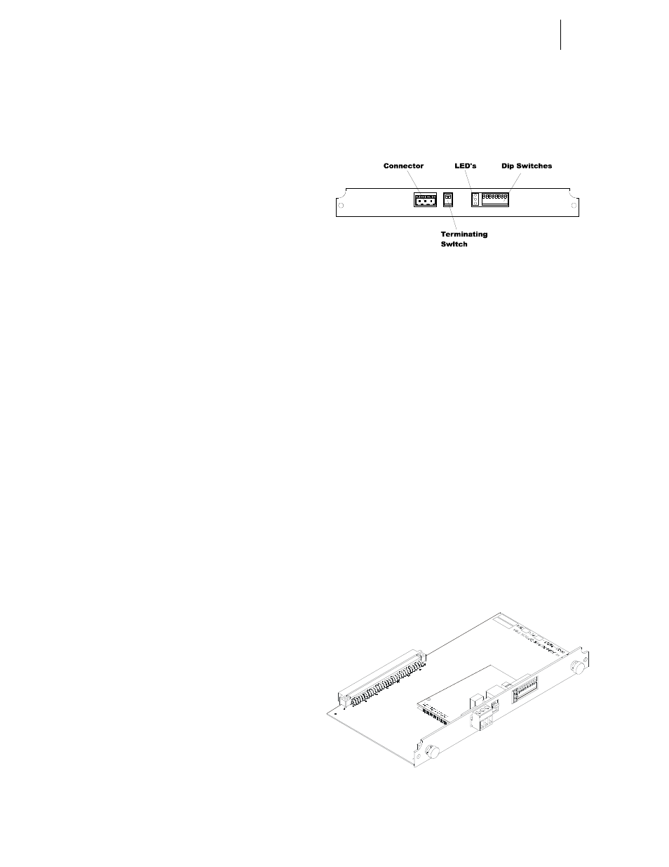
Step 1. The Terminating Switch is accessible from the rear
of the HI 3000 Series Module. (See Fig. 3)
FIG. 3: TERMINATING SWITCH FOR
TERMINATING LAST MODULE
Step 2. On the first module and the last module turn the ter-
minating switch to ON.
Step 3. For all other devices on the daisy chain the termi-
nating must be set to OFF.
Dip Switch Settings
Set all the Dip Switch Settings to ON. (See Fig. 3)
Installing the RIO Option Board
CAUTION: M
AKE
SURE
THAT
YOU
USE
AN
ANTI
-
STATIC
STRAP
WHEN
INSTALLING
THE
R
EMOTE
I/O O
PTION
C
ARD
.
Step 1. Position the RIO Option Card with the back plane
connector facing Option Slot #0. (See Fig. 4)
NOTE:
You can only use Option Slot #0 when installing
the RIO Option Card.
FIG. 4: REMOTE I/O OPTION CARD
Step 2. Slide the RIO Option Card into Slot #0. (See Fig. 5)