Fig. 5: remote i/o/slide into option slot #0, Fig. 6: remote i/o option card installed, Connector pin out – Hardy HI 3010 Filler/Dispenser Controller User Manual
Page 19: Led indicators, Removing the remote i/o option card, Fig. 7: configuration menu/selecting setup, Emote i/o/slide into option slot #0, Emote i/o option card installed, Onfiguration menu/selecting setup
5
Communications
Installation & Operation
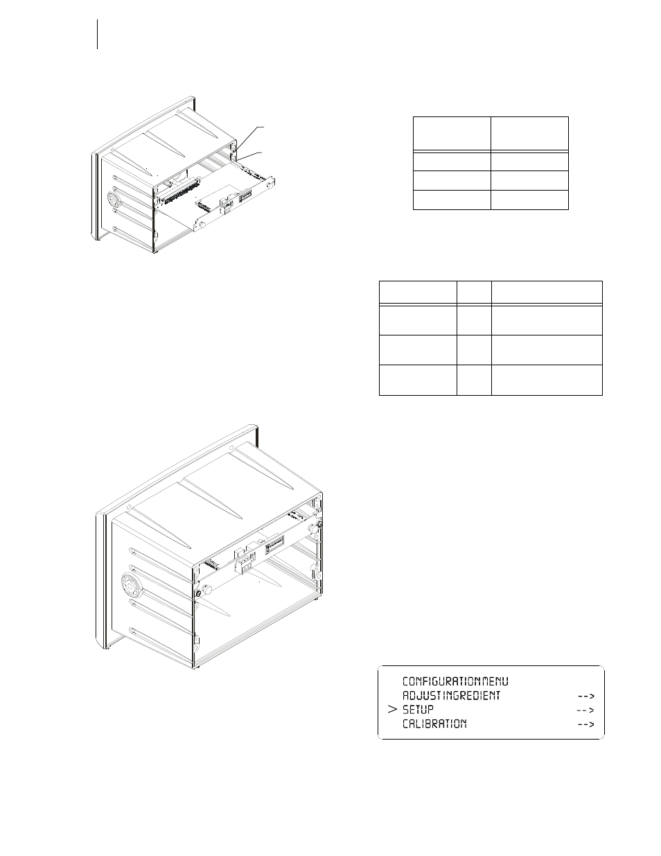
FIG. 5: REMOTE I/O/SLIDE INTO OPTION SLOT #0
Step 3. Push the Remote I/O card up against the back plane
and gently press until the card connector seats in the
back plane connector.
Step 4. Use a phillips head screw driver and install the two
(2) screws that fasten the RIO card panel to the HI
3000 Instrument Chassis. (See Fig. 6)
Step 5. Tighten the screws until the RIO panel is snug. Do
not overtighten.
FIG. 6: REMOTE I/O OPTION CARD INSTALLED
Step 6. Connect the Remote I/O cable to the 3 pin connec-
tor on the RIO board.
Step 7. Connect the other end of the Remote I/O cable to
the PLC, SLC or PC Remote I/O Interface card.
Connector Pin Out
LED Indicators
Removing the Remote I/O Option Card
Step 1. Disconnect the cables.
Step 2. Use a phillips head screw driver and remove the
two (2) screws that fasten the RIO Option Card
panel to the HI 3000 Chassis.
Step 3. Using the thumb and index finger on both hands,
grasp the two (2) knobs on the RIO Card panel and
pull away from the instrument.
Step 4. When the RIO Option Card clears the chassis, store
in a static free, safe location.
Remote I/O Configuration Procedures from the
Front Panel
Step 1. At the front panel click on the Setup/3 button. The
Configuration Menu appears. (See Fig. 7)
FIG. 7: CONFIGURATION MENU/SELECTING
SETUP
Option Slot 1
Option Slot 0
Screw Terminal
(3-pin)
Description
1
Blue
2
Shield
3
Clear
TABLE 1: SCREW TERMINAL (3-PIN) PIN OUT
LED
Color
Function
Error
(Top LED)
Red
Off: Normal Operation
On: Bus off/error
Power
(Bottom LED)
Green
Off: Power is Off
On: Power is On
Active
(Middle LED)
Green
Off: No Communication
On: Communication Active
TABLE 2: LED INDICATORS