Lecting hardy control-link, Onfiguration - hardy control-link/instrument, Lected instrument with ip address in – Hardy HI 3010 Filler/Dispenser Controller User Manual
Page 52: Rdy modbus-link display/writer multiple, Ardy modbus-link/enter value display, Lect module type
HI-3000 Series
38
Operation and Installation
•
Ethernet Cables with RJ45 connectors on
both ends.
Step 1. Connect the Standard Ethernet cables between all
the HI 3000 instruments and the hub or Switch.
Step 2. Connect the a Standard Ethernet cable between the
PC and the Hub or Switch.
Step 3. Create an IP address for each of the HI 3000 Series
instruments and the PC. (See Cabling: Installation/
Ethernet Cable Connection and Setup Section in
this manual). (For the PC see Simple Ethernet Net-
work above.)
Step 4. Start your computer.
Step 5. Start the Browser and type the IP address of the
instrument you want to monitor or configure.
Setting Node Addresses for HI 3000 Series
Instruments from the Browser
Step 1. From the HI 3000 Series instrument Home Page
click on Configuration. (See Fig. 98) The Configu-
ration page appears. (See Fig. 99)
NOTE:
We are showing the HI 3010 Filler/Dispenser
however all HI 3000 Series instruments are con-
figured the same way.
FIG. 98: FILLER/DISPENSER HOME PAGE/
SELECTING CONFIGURATION
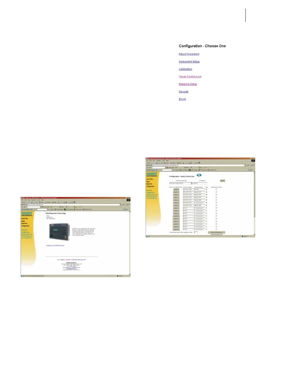
FIG. 99: CONFIGURATION PAGE/SELECTING
HARDY CONTROL-LINK
Step 2. Click on “Hardy Control-Link”. The Configuration
- Hardy-Link Page appears. (See Fig. 100)
FIG. 100: CONFIGURATION - HARDY CONTROL-
LINK PAGE
Step 3. If other HI 3000 Controllers are attached to the
Hardy Control-Link Network, you can view their IP
addresses by clicking on the “Instrument Selection”
pull down list. All connected devices are listed.
(See Fig. 101)