Cabling: installation, General introduction to cabling, Unpacking – Hardy HI 3010 Filler/Dispenser Controller User Manual
Page 25: Input power wiring, Fig. 20: power wiring diagram, Digital input wiring, Fig. 21: power supply board rear panel, Cabling, Y board rear panel, Rotary switches/se
11
Cabling
Installation
CABLING: INSTALLATION
General Introduction to Cabling
This section pertains to unpacking the instrument and instal-
lation of the Power, Load Cells, DeviceNet and Ethernet
Cables. For more detailed installation information please
refer to the HI 3000 Series Service Manual. For specification
information please read the HI 3000 Series Service Manual.
It is highly recommended that the user follow the installation
instructions either implied or explicitly stated in this section
to insure the instrument operates as designed.
Unpacking
Step 1. Before signing the packing slip, inspect the packing
for damage of any kind.
Step 2. Report any damage to the carrier company immedi-
ately.
Step 3. Check to see that everything in the package
matches the bill of lading.
Step 4. If any items are missing, damaged, or you have any
questions, please contact Technical Support at:
Hardy Process Solutions.
9440 Carroll park Drive
San Diego, CA 92121
Phone: (858) 278-4900
FAX: (858) 278-6700
Web Site: http://www.hardysolutions.com
E-Mail: [email protected]
Step 5. Record the model number and serial number of the
Filler/Dispenser Controller. Store in a convenient,
secure location for reference when contacting
Hardy Technical Support Department or to buy
parts or firmware upgrades.
Input Power Wiring
WARNING:
DO
NOT
OPERATE
WITH
INCORRECT
LINE
VOLTAGE
.
TO
DO
SO
WILL
RESULT
IN
PROPERTY
DAMAGE
AND
/
OR
PERSONAL
INJURY
. M
AKE
SURE
THAT
THE
POWER
SOURCE
DOES
NOT
EXCEED
240 VAC.
•
The AC power should be supplied by a “clean” primary
line, directly from the power panel. This line should not
supply any other equipment, including the feeding unit,
and should be supplied with a minimum 10 amp breaker.
(See Fig. 20)
FIG. 20: POWER WIRING DIAGRAM
•
Power Input J1
J1-1 Neu (Low)
J1-2 Line (HI)
J1-3 Ground
Step 1. The HI 3000 Series instruments are configured with
a universal power supply rated from 120 to 240
VAC. The instruments can be powered by a 120 or
240 VAC power source and requires no switching
or jumper settings.
Step 2. Install a 3-wire, minimum 14 AWG power line to
the 3-pin terminal block connector. (See Fig. 20)
Step 3. The power and relay circuit card filters and condi-
tions AC power. However, for noisy power lines,
external conditioning may be required. For more
information, consult the HI 3000 Series Installation
and Service Manual or contact Hardy Instruments
Technical Support.
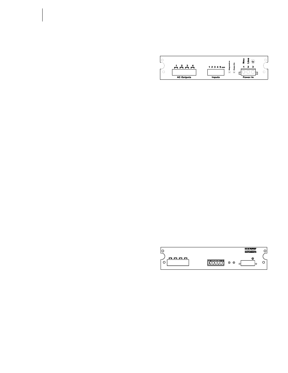
Digital Input Wiring
The 5 digital inputs to the HI 3000 series instruments are
mappable inputs and are only active when connected to
ground. (See Fig. 21)
FIG. 21: POWER SUPPLY BOARD REAR PANEL
WARNING: N
O
V
OLTAGE
EXCEPTED
AS
AN
INPUT
DRIVER
. D
O
NOT
WIRE
110 V
OLTS
INTO
THE
DIGITAL
INPUTS
. T
O
DO
SO
WILL
CAUSE
PROPERTY
DAMAGE
AND
/
OR
PERSONAL
INJURY
.
Step 1. Connect the input wire to the selected input.
Step 2. Connect the input wire to some form of dry contact
switch. (See Fig. 22)
Power In
Po
w
e
r O
n
D
iag
nos
ti
cs
Inputs
Gnd
1
2
3
4
5
Ne
u
Li
ne
www.hardyinst.com/3000
2
3
4
1
Outputs