Hardy HI 3010 Filler/Dispenser Controller User Manual
Quick installation guide
QUICK INSTALLATION GUIDE
Mechanical Installation
Installing the HI 3010 Filler/Dispenser/IBC in a Panel
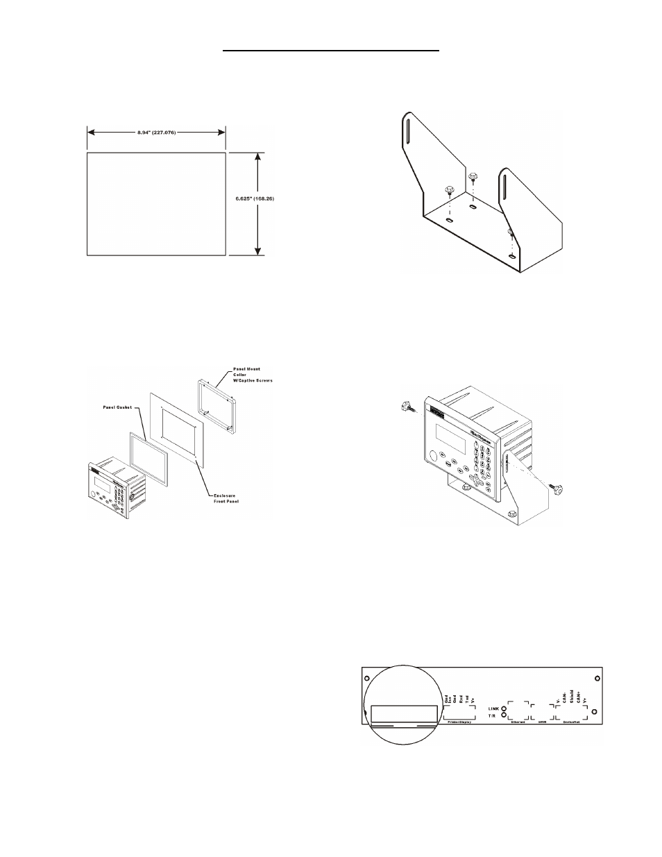
FIG. 1 PANEL CUTOUT DIMENSIONS
Step 1.
Make sure that all Electrostatic Discharge (ESD) precautions
are taken before and during installation.
Step 2.
Slide the gasket over the rear of the instrument until the gasket
is flush with the back side of the front panel. (See Fig.2)
FIG. 2 PANEL MOUNT INSTALLATION
Step 3.
Gently slide the Filler/Dispenser with the gasket into the cut-
out in the enclosure front panel or door until the gasket is flush
with the enclosure front panel. (See Fig. 3-4) Be sure to secure
the instrument with both hands when installing.
Step 4.
Gently slide the Panel Mount Collar over the rear of the instru-
ment. (See Fig. 2)
Step 5.
Push the captive screws through the holes in the Enclosure
Front Panel and install the screws into the tapped holes on the
instrument until the screws are finger tight.
Step 6.
Use a slotted head screwdriver and tighten each screw until the
instrument is snug and the compression gasket is tight against
the panel. Use a torque screw driver and torque each screw to
10 inch/pounds. DO NOT OVERTIGHTEN!
Installing the HI 3010 Filler/Dispenser/IBC in a Swivel/
Wall Mount
NOTE:
When wall mounted, the unit should support a 14
pound weight for one minute without coming loose or
damaging the equipment.
Step 1.
Use four (4) 1/4 x 20 fasteners to fasten the swivel mount to a
horizontal surface. (See Fig. 3)
FIG. 3 INSTALLING THE SWIVEL MOUNT TO A HORIZON-
TAL SURFACE
Step 2.
Place the Filler/Dispenser between the Swivel Mount brackets
so that the threaded holes in the instrument are aligned with
the slots in the Swivel bracket. (See Fig.4)
FIG. 4 FILLER/DISPENSER INSTALLING IN A SWIVEL
MOUNT
Step 3.
Screw the two fastener knobs into the threaded holes on each
side of the Filler/Dispenser until the brackets are snug against
the instrument. (See Fig. 5)
Load Point Installation
FIG. 5 REAR PANEL/LOAD POINT CONNECTIONS
Document Outline
- Quick Installation guide
- Mechanical Installation
- Installing the HI 3010 Filler/Dispenser/IBC in a Panel
- FIG. 1 panel cutout dimensions
- FIG. 2 panel mount installation
- Step 3. Gently slide the Filler/Dispenser with the gasket into the cutout in the enclosure front panel or door until the gasket is flush with the enclosure front panel. (See Fig. 3-4) Be sure to secure the instrument with both hands when installing.
- Step 4. Gently slide the Panel Mount Collar over the rear of the instrument. (See Fig. 2)
- Step 5. Push the captive screws through the holes in the Enclosure Front Panel and install the screws into the tapped holes on the instrument until the screws are finger tight.
- Step 6. Use a slotted head screwdriver and tighten each screw until the instrument is snug and the compression gasket is tight against the panel. Use a torque screw driver and torque each screw to 10 inch/pounds. DO NOT OVERTIGHTEN!
- Installing the HI 3010 Filler/Dispenser/IBC in a Swivel/ Wall Mount
- C2® Load Point Connection
- WARNING: Load cell cable length has been calculated into C2 calibration data. Hardy recommends that you do not cut your Advantage or Advantage Lite load sensor cable, as your C2 accuracy will be affected and the warranty will be voided.
- Step 1. Remove the factory installed jumper from the terminal block if you are connecting an 8 wire cable from the junction box.
- Step 2. Connect the cable (Recommended load cell cable: Hardy Instruments Prt. # 6020-0001) wires to the J9 terminal block according to the cable color chart.
- Step 3. Plug the terminal block into the Channel 1 connector on the rear panel.
- Step 4. For more information concerning C2 Load Point connection, consult the HI 3000 Series Installation and Service Manual.
- Non-C2 Load Point Connection
- Step 1. Remove the factory installed jumper from the terminal block if you have 6 wire load cell cable that includes sense wires from the load cell or junction box.
- Step 2. Connect the cable (Recommended load cell cable: Hardy Prt. # 6020-0001) wires to the Channel 1 terminal block according to the Non-C2 cable color chart, or per manufacturers specification.
- Step 3. Plug the terminal block into the Channel 1 (J9) connector on the rear panel.
- AC Input Power Wiring
- WARNING: do not operate with incorrect line voltage. to do so will result in property damage and/or personal injury. Make sure that the power source does not exceed 240 VAC.
- FIG. 6 power wiring diagram
- FIG. 7 Press enter
- FIG. 8 application selection
- Step 5. Refer to the User Guide, Section 1 of the HI 3010 Filler/Dispenser/IBC for information about Typical Applications.
- Step 6. Press the up or down arrow buttons until the cursor is in front of the application you want.
- Step 7. Press Enter. The application you select will install with default parameters.