Initialization procedures, Fig. 142: anybus-s pdp parameters dialog box, Are catalog/selecting anybus-s pdp folder – Hardy HI 3010 Filler/Dispenser Controller User Manual
Page 64: Ters dialog box
HI-3000 Series
50
Operation and Installation
Step 2. Select the Node address for the HI 3000 Series.
(See below) This can be done before or after Initial-
ization.
Step 3. Cycle power, or perform the two previous steps
before powering up your network. Address selec-
tion can only occur after cycling the power. Make
sure that the software you use will detect the values
as you have set them.
CAUTION: T
HE
ADDRESS
SHOULD
NEVER
BE
CHANGED
DURING
OPERATION
. I
F
THE
ADDRESS
IS
MODIFIED
WHILE
THE
POWER
IS
ON
,
AN
INTERNAL
ERROR
COULD
BE
GEN
-
ERATED
AND
THE
MODULE
DISCONNECTED
FROM
THE
NET
-
WORK
.
NOTE:
Profibus-DP provides a very flexible network
solution. In addition to the basic guideline pro-
vided in this manual, your installation could
require procedures that are beyond the scope of
this manual. For more information and to locate
lists of links to other sources of Profibus-DP
information, check the Profibus website at http://
www.profibus.com.
Step 4. Complete any additional configuration that is
required by your PLC for initialization. Our initial-
ization example is for a Siemens PLC. Your PLC
initialization requirements may differ.
Step 5. Install the *.GSD file for the HI 3000 Series Instru-
ment you connected to the Profibus Network.
Initialization Procedures
NOTE:
The examples provided are taken from the Sie-
mens Step 7™, Simatic Manager Software. Your
software will vary from these procedures. Step
7™ is a trademark of the Siemens Corporation.
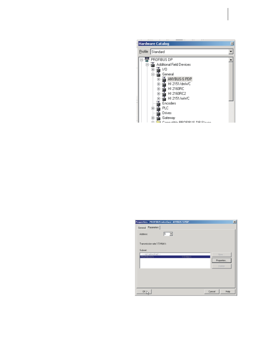
Step 1. In the Siemens Step 7™, Simatic Manager open the
Hardware Catalog. (See Fig. 141)
FIG. 141: HARDWARE CATALOG/SELECTING
ANYBUS-S PDP FOLDER
Step 2. Click on the “+” to expand the Additional Field
Devices Folder. (See Fig. 141)
Step 3. Click on the “+” to expand the General Folder. (See
Fig. 141)
Step 4. Highlight the CPU you selected in the UR dialog
box.
Step 5. Double Click on ANYBUS-S PDP or drag and drop
the ANYBUS-S PDP folder to the Profibus-DP
Network. The Parameters dialog box appears. (See
Fig. 142)
Step 6. You can set the address of the instrument here if
necessary.
FIG. 142: ANYBUS-S PDP PARAMETERS DIALOG
BOX
Step 7. Click on “+” to expand the ANYBUS-S PDP
folder. (See Fig. 143)