2 preparing the 8400 baseline for commissioning, Preparing the 8400 baseline for commissioning, 3commissioning – Lenze 8400 BaseLine C User Manual
Page 26: Danger
3
Commissioning
3.2
Preparing the 8400 BaseLine for commissioning
26
Lenze · 8400 BaseLine C · Reference manual · DMS 1.6 EN · 01/2014 · TD05
_ _ _ _ _ _ _ _ _ _ _ _ _ _ _ _ _ _ _ _ _ _ _ _ _ _ _ _ _ _ _ _ _ _ _ _ _ _ _ _ _ _ _ _ _ _ _ _ _ _ _ _ _ _ _ _ _ _ _ _ _ _ _ _
3.2
Preparing the 8400 BaseLine for commissioning
1. Wiring the power connections
• Refer to the mounting instructions supplied with the drive controller to find help on how to
correctly design the power connections to match the requirements of your device.
2. Wire the control connections
• The following shows the wiring for the Lenze setting.
3. Inhibit the controller:
Set terminal X4/RFR to LOW level or open contact to terminal X4/12I .
4. Switch on voltage supply of the controller.
• Information on some operating states can be quickly obtained via the LED display of the in-
tegrated keypad.
When the green LED is blinking and the red LED is off, the controller is ready to start and you can
continue with commissioning as required:
Commissioning with integrated keypad
or
Commissioning with the »Engineer«
Danger!
Take all the necessary safety precautions before you carry out the following commissio-
ning steps and switch the device on!
Safety instructions with regard to commissioning
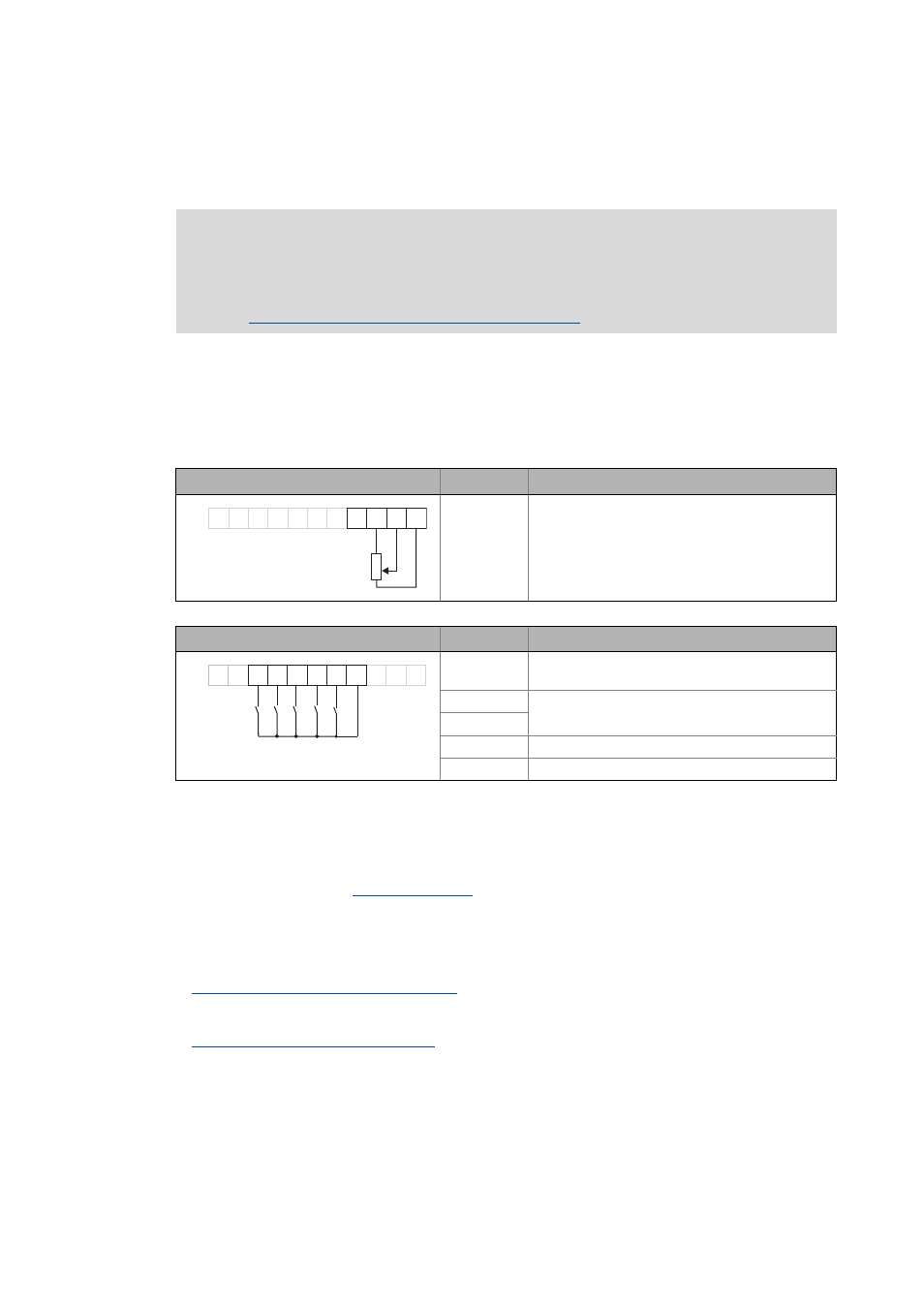
Analog input at X4
Terminal Function
A1U Setpoint selection
• Scaling: 10 V ≡ 100 % ≡ 1500 rpm
(for 4-pole motor)
Digital inputs at X4
Terminal Function
DI1 ... DI4: All HIGH active
RFR Controller enable: HIGH level
Error reset: HIGH-LOW edge
DI1 Selection fixed setpoint 1 ... 3
DI2
DI3 Request DC-injection braking (DCB)
DI4 Request change of direction of rotation
DI1
DI2
DI3
DI4
RFR
X4
24E
DO1
12I AR A1U GND
0
10V
...
1k
10k
W
...
W
AR A1U GND
DI1
DI2
DI3
RFR
X4
DO1
12I
24E
DI4