4 electrical data, Electrical data, 6i/o terminals – Lenze 8400 BaseLine C User Manual
Page 119: X101
Lenze · 8400 BaseLine C · Reference manual · DMS 1.6 EN · 01/2014 · TD05
119
6
I/O terminals
6.4
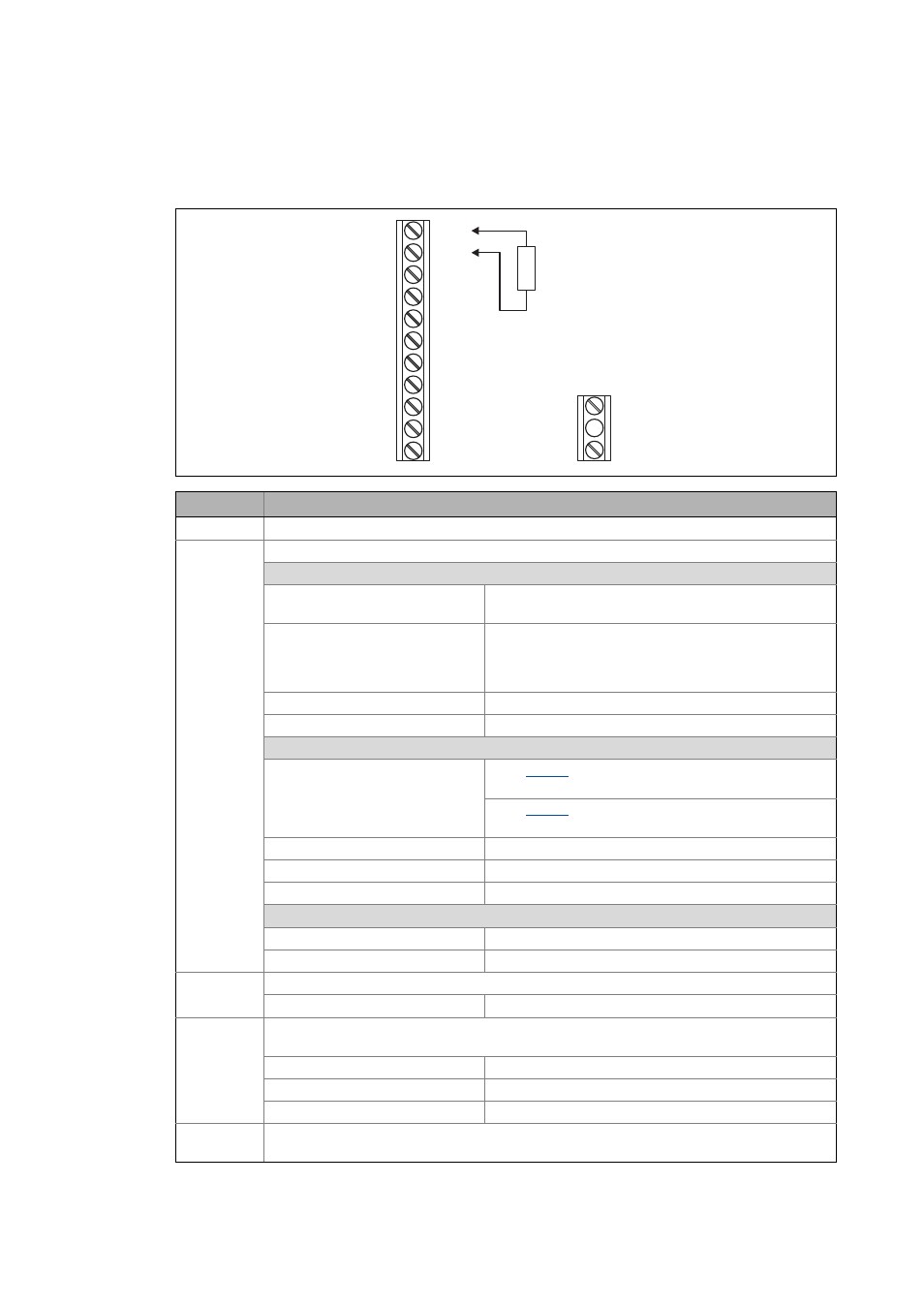
Electrical data
_ _ _ _ _ _ _ _ _ _ _ _ _ _ _ _ _ _ _ _ _ _ _ _ _ _ _ _ _ _ _ _ _ _ _ _ _ _ _ _ _ _ _ _ _ _ _ _ _ _ _ _ _ _ _ _ _ _ _ _ _ _ _ _
6.4
Electrical data
Terminal
Application / electrical data
GND
Reference potential
A1U
Voltage or current input
General data:
Resolution: 10 bits
(Error: 1 digit ≡ 0.1 %, in relation to the final value)
Conversion rate: 1 kHz
In order to filter short-time faults in the analog signal charac-
teristic, the analog input value is led via a digital lag filter
with a time constant of 5 ms.
Processing cycle: 1 kHz (1 ms)
Electric strength of external voltage: ±15 V, permanent
If used as voltage input:
Level/scaling: When
= "0":
0 ... +10 V ≡ 0 ... +2
14
≡ 0 ... +16384 ≡ 0 ... +100 %
When
= "1" or "2":
0 ... +5 V ≡ 0 ... +2
14
≡ 0 ... +16384 ≡ 0 ... +100 %
Input resistance: > 50 kΩ
Input voltage in case of open circuit: Display "0" (V< 0.2 V, absolute)
Accuracy: ±0.1 V
If used as current input (with external 250-Ω load resistor; see illustration):
Level/scaling: 0 ... +20 mA ≡ 0 ... +2
14
≡ 0 ... +16384 ≡ 0 ... +100 %
Input resistance: 250 Ω (external)
AR
10-V reference voltage for analog input
maximum output current: 10 mA
12I
12 V voltage for connecting the digital inputs via potential-free contacts
• Internal supply: DC
maximum output current: 50 mA
Electric strength of external voltage: +30 V
Overcurrent protection: Automatic reset
RFR
Controller enable
• Electrical data as in digital inputs
X4
GND
A1U
AR
12I
RFR
DI1
DI2
DI3
DI4
24E
DO1
R = 250
B
W
X101
NO
COM