3 internal keypad, 1 display elements and control panel, Internal keypad – Lenze 8400 BaseLine C User Manual
Page 17: Display elements and control panel, 2introduction: parameterising the controller
Lenze · 8400 BaseLine C · Reference manual · DMS 1.6 EN · 01/2014 · TD05
17
2
Introduction: Parameterising the controller
2.3
Internal Keypad
_ _ _ _ _ _ _ _ _ _ _ _ _ _ _ _ _ _ _ _ _ _ _ _ _ _ _ _ _ _ _ _ _ _ _ _ _ _ _ _ _ _ _ _ _ _ _ _ _ _ _ _ _ _ _ _ _ _ _ _ _ _ _ _
2.3
Internal Keypad
The controller front is provided with an integrated keypad. Use the keypad for quick and simple pa-
rameter setting and for displaying current actual values and device states via the respective display
parameters.
2.3.1
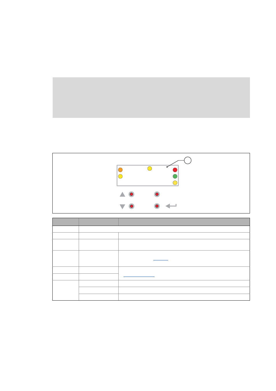
Display elements and control panel
Important status information of the controller is displayed optically by LEDs. The positions of the co-
loured LEDs are marked on the housing by letters.
Note!
After switching on the controller, the internal keypad performs a quick self-test. All seg-
ments of the display flash. After the self-test, the keypad shows "rdy" for a short time
and then changes to the display of the setpoint speed of the motor. The keypad is now
ready for operation.
Symbol
Information
Meaning
4-character display with LEDs (A ... F)
A
orange
Set current/torque limit is reached
B
yellow
Minus sign for identifying the negative numbers bigger than 4 characters
when the rotational direction has been reversed.
C
yellow
User LED
• configurable via
• user-defined LED status
D
red
DRIVE ERROR / DRIVE READY
E
green
F
yellow
Direction of rotation: CCW rotation
Off
Direction of rotation: CW rotation
blinking
Commanded direction is not equal to actual direction (e.g. during reversing)
8888
B
ESC
C
D
E
F
A
1