L-force | plc designer - softmotion – Lenze PLC Designer PLC-Designer (R2-x) SoftMotion User Manual
Page 277
DMS 5.2 EN 03/2011 TD17
L
277
L-force | PLC Designer - SoftMotion
SoftMotion programming examples
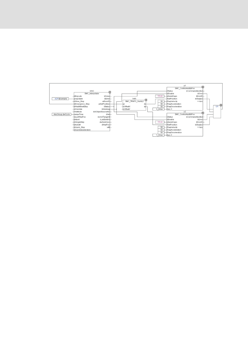
Drive control with the aid of the CNC editor
– The outputs of the program organisation unit, i.e. the axis coordinates, now have to
be written to the drives, which is what the SMC_ControlAxisByPos function blocks
are for. As this application does not guarantee that the interpolator outputs will be
continuous (e.g. the path may end at a different point to where it starts), you must
activate functions that avoid gaps (bAvoidGaps, fGapVelocity, fGapAcceleration,
fGapDeceleration), connect the StopIpo output to the interpolator's
bEmergency_Stop and connect the iStatus interpolator output to the corresponding
inputs of the axis control program organisation units.
– Please note that the program organisation units must be in the correct order,
particularly when programming with CFC.
4. Creating the operation and test interface:
– Create a new visualisation and insert two visualisation objects (the interpolator
template and the transformation template) into it. These are connected to the
corresponding POU instances (here: Ipo.smci or Ipo.trafof) by means of the
placeholder concept.
5. Commissioning:
– The program created in this way can be compiled without errors and started. It will
execute the CNC program as soon the Execute input of the interpolator is set. Once
it has been processed completely, a new rising edge will cause the program to run
again.
– Please also note the function of the path switches, which are also displayed in the
visualisation of the interpolator program organisation unit.