7 spatial transformations, Spatial transformations, L-force | plc designer - softmotion – Lenze PLC Designer PLC-Designer (R2-x) SoftMotion User Manual
Page 238
L-force | PLC Designer - SoftMotion
The SM_Trafo.lib library
Transformation function blocks
238
L
DMS 5.2 EN 03/2011 TD17
9.1.7
Spatial transformations
In some cases the machine and workpiece have different coordinate systems. The
transformation POUs of the SM_Trafo.lib library transform the Cartesian coordinates of
the tool point into machine coordinates. Prior to this, however, if the workpiece is not
oriented exactly in accordance with the CNC program, it may be necessary to transform the
path coordinates calculated by the interpolator before passing them on to the machine
transformation.
Imagine a standard gantry (X/Y/Z). The tool point of the gantry must be moved across the
surface of a workpiece that is positioned transversely in space:
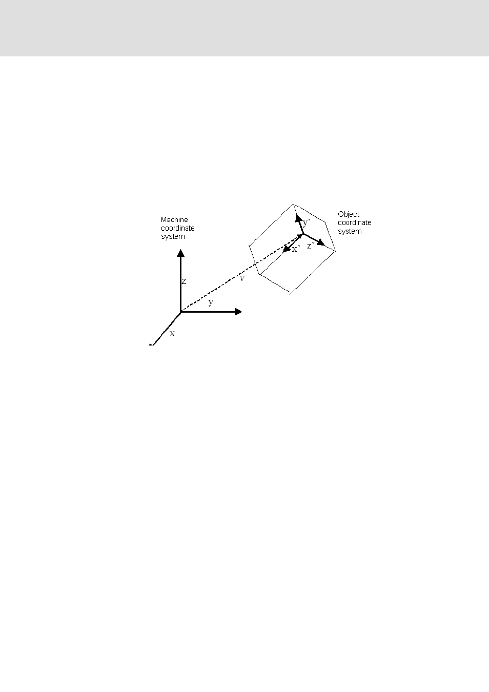
There are several options available for describing the relationship between two coordinate
systems. A coordinate transformation always consists of a spatial translation and a spatial
rotation. The translation is described by a three-dimensional vector, the rotation either by
three angles (e.g. YawPitchRoll) or by the three unit vectors of the new (object) coordinate
system x', y', z'.
If the method using the three rotation angles is selected, these can be defined according to
the Roll/Pitch/Yaw (RPY) convention, for example. In this case the new coordinate system
results from the old one by means of a rotation around various axes. The RPY (a, ß, ?) can
operate in two ways, both of which provide the same result:
1. Starting from the coordinate system (x,y,z), rotate the coordinate system around the z
axis by angle ß in a mathematically positive direction. This will produce the new
coordinate system (x1, y1, z1=z). Now fix axis y1 of the new coordinate system and
rotate the system around ß, which will produce (x2, y2=y1, y2). Finally, rotate this
coordinate system around x2 by angle a, thus producing (x'=x2, y', z').
2. Starting from the coordinate system (x,y,z), rotate the coordinate system around the x
axis by angle a. Rotate the resulting coordinate system (Aa=x, ya, ya) around the
original y axis (not ya!) by ß (xb, yb, zb) and then around the original z axis by ?, which
will produce (x', y', z').