3 candrive, Candrive, Candrive ( 22) – Lenze PLC Designer PLC-Designer (R2-x) SoftMotion User Manual
Page 22
L-force | PLC Designer - SoftMotion
The SoftMotion drive interface
Control configuration for SoftMotion
22
L
DMS 5.2 EN 03/2011 TD17
3.1.3
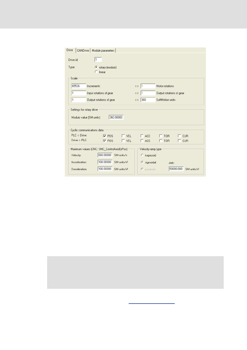
CANDrive
In this dialog the drive ID (Drive ID) is defined. Furthermore the drive type is selected: linear
or rotary (modulo).
In the Conversion factor area the conversion between the integer position values received
by the drive (first line on the left) and the technical units used in the IEC program (first line
on the right) is defined. Set the value 65536 in the Increments input field. Here also a
gearbox can be taken into consideration (second and third line). In the above example a
drive would exactly carry out a mechanical revolution if 360 degrees were programmed.
Depending on the drive type selected, software limit switches can be defined in the area
Settings for linear drive for linear drives, or the modulo range has to be defined for rotary
drives.
In the cyclic communication data area is it selected which setpoint and actual data are to
be transmitted cyclically between the control system (PLC) and the drive.
Under Maximum values the limit values are set which are used by SMC_ControlBy blocks
to determine whether there is a skip (see
).
Note!
ECSxM (motion) Lenze controllers only support the transmission of position
values in the cyclic communication data. If these controllers are used, therefore
no further cyclic data must be activated.